Reference genlock d-connector – Grass Valley PDR 200 Service Manual User Manual
Page 163
Reference Genlock D-Connector
PDR 200 Installation Manual
A-7
Reference Genlock D-Connector
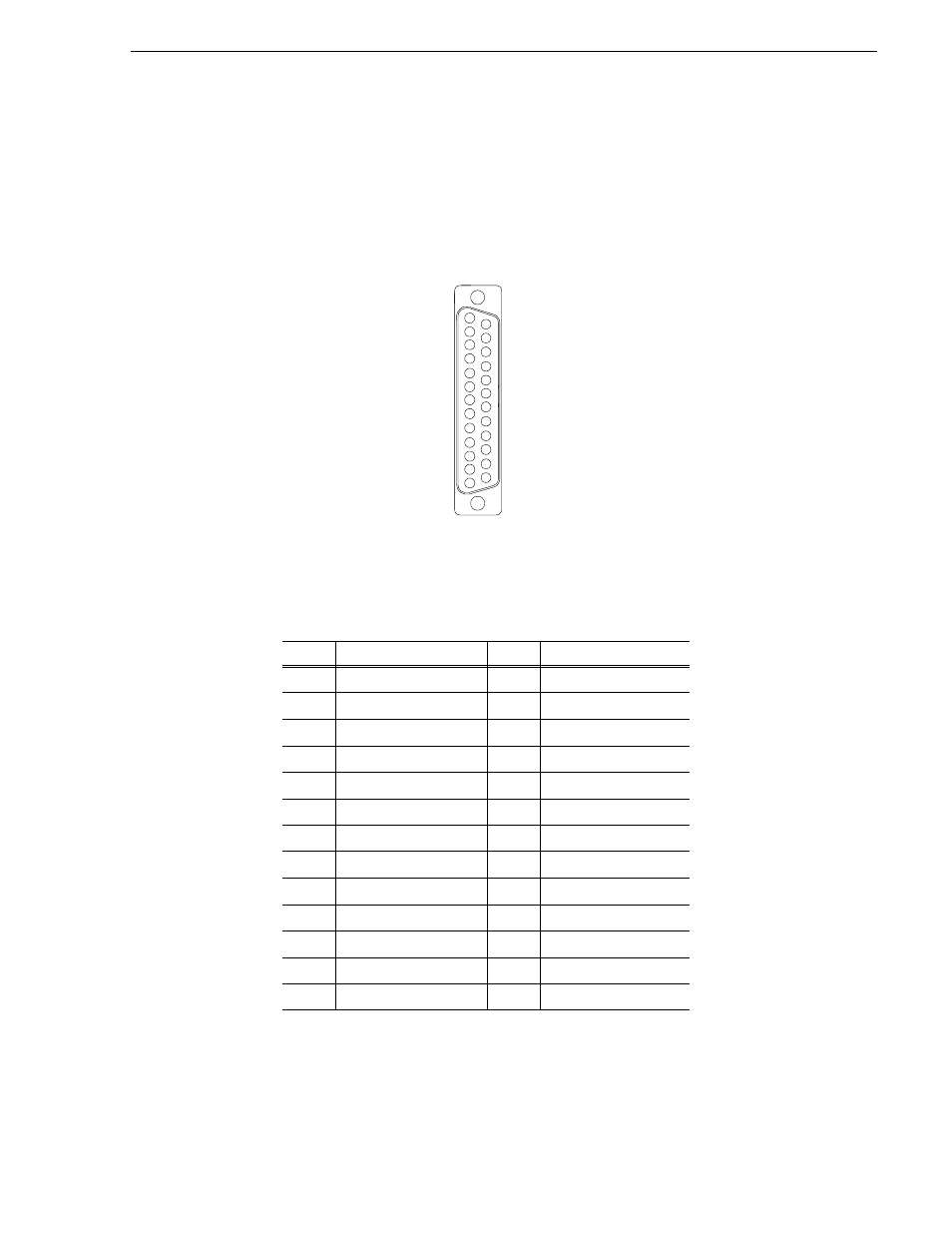
The 25-pin D connector on the Reference Genlock board provides eight Longitudinal
Time Code (LTC) interfaces (four input channels and four output channels). The LTC
Breakout cable with a DB25 connector on one end and eight XLR connectors on the
other can then be connected to the Reference Genlock 25-pin D connector at the rear
panel of the Profile. Figure A-5 shows the connector and Table A-7 lists the pin-outs.
Figure A-5. Reference Genlock 25-pin Connector
Table A-7. Reference Genlock D-connector Pin-outs
Pin #
Description
Pin #
Description
1
Ch 0 Input +
14
Ch 0 Output Common
2
Ch 0 Input -
15
Ch 0 Output +
3
Ch 0 Input Common
16
Ch 0 Output -
4
Ch 1 Input +
17
Ch 1 Output Common
5
Ch 1 Input -
18
Ch 1 Output +
6
Ch 1 Input Common
19
Ch 1 Output -
7
Ch 2 Input +
20
Ch 2 Output Common
8
Ch 2 Input -
21
Ch 2 Output +
9
Ch 2 Input Common
22
Ch 2 Output -
10
Ch 3 Input +
23
Ch 3 Output Common
11
Ch 3 Input -
24
Ch 3 Output +
12
Ch 3 Input Common
25
Ch 3 Output -
13
Power On Indicator
1
13
14
25