Tod synchronizer block – Altera Triple Speed Ethernet MegaCore Function User Manual
Page 208
ToD Synchronizer Block
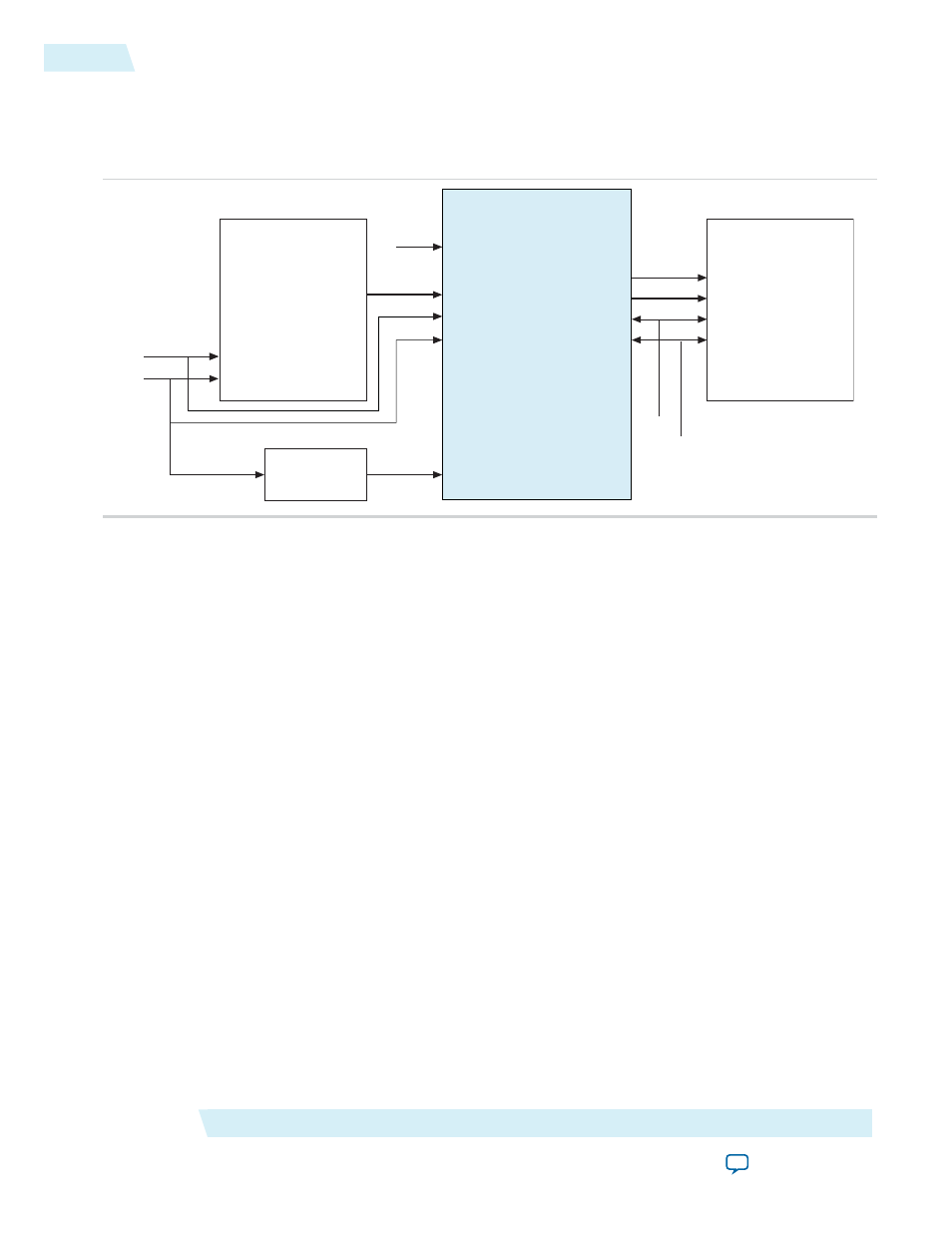
Figure D-1: Connection between ToD Synchronizer, Master ToD, Slave ToD, and Sampling Clock PLL
Slave ToD
time_of_day_96b_load_valid
time_of_day_96b_load_data
period_rst_n
period_clk
ToD Synchronizer
tod_master_data
reset_master
clk_master
tod_slave_valid
Synchronization valid
Synchronization ToD
tod_slave_data
reset_slave
clk_slave
clk_sampling
start_tod_sync
Master ToD
PLL
time_of_day_96b
Master ToD
1’b1
Sampling clock
Master reset
Slave reset
Master clock
Slave clock
period_rst_n
period_clk
The components:
• Master TOD clock domain—consists of three interfaces:
clk_master
,
reset_master
, and
tod_master_data
.
• Slave TOD clock domain—consists of five interfaces:
clk_slave
,
reset_slave
,
tod_slave_valid
,
tod_slave_data
, and
start_tod_sync
.
• Sampling clock PLL—consists of the
clk_domain
interface.
The Tod synchronizer module synchronizes the master ToD clock domain with the slave ToD clock domain.
The dual-clock FIFO in the Tod synchronizer block takes in the time of day from the master ToD clock
domain and transfers it to the slave ToD clock domain. The slave ToD then will load the synchronized time
of day into its own internal counter, which then increments based on the new value.
As the ToD transfer is in progress, the master ToD domain keeps incrementing. When the ToD reaches the
slave ToD clock domain and is ready to be loaded, it is much slower than the master ToD. To achieve high
accuracy synchronization, the latency caused by the transfer must be reflected in the synchronized ToD.
The sampling clock PLL (
clk_sampling
) samples the FIFO fill level and calculates the latency through the
FIFO. For better accuracy, the sampling clock must be derived from the master (
clk_master
) or slave
(
clk_slave
) clock domain using a PLL.
If you use the recommended sampling clock frequency, the Tod synchronizer module takes 64 clock cycles
of sampling clock for every newly synchronized ToDto be valid at the output port.
Altera recommends that you use the following sampling clock frequencies:
• 1G master and slave—(64/63)*125 MHz
• 10G master and slave—(64/63)*156.25 MHz
• 1G master and 10G slave—(16/63)*125 MHz or (64/315)*156.25 MHz
• 10G master and 1G slave—(16/63)*125 MHz or (64/315)*156.25 MHz
• 10G (312.5 Mhz) master and slave—(64/63)*312.5 MHz
ToD Synchronizer
Altera Corporation
UG-01008
ToD Synchronizer Block
D-2
2014.06.30