Pcs control interface signals, Pcs reset signals, Mii/gmii clocks and clock enablers – Altera Triple Speed Ethernet MegaCore Function User Manual
Page 150
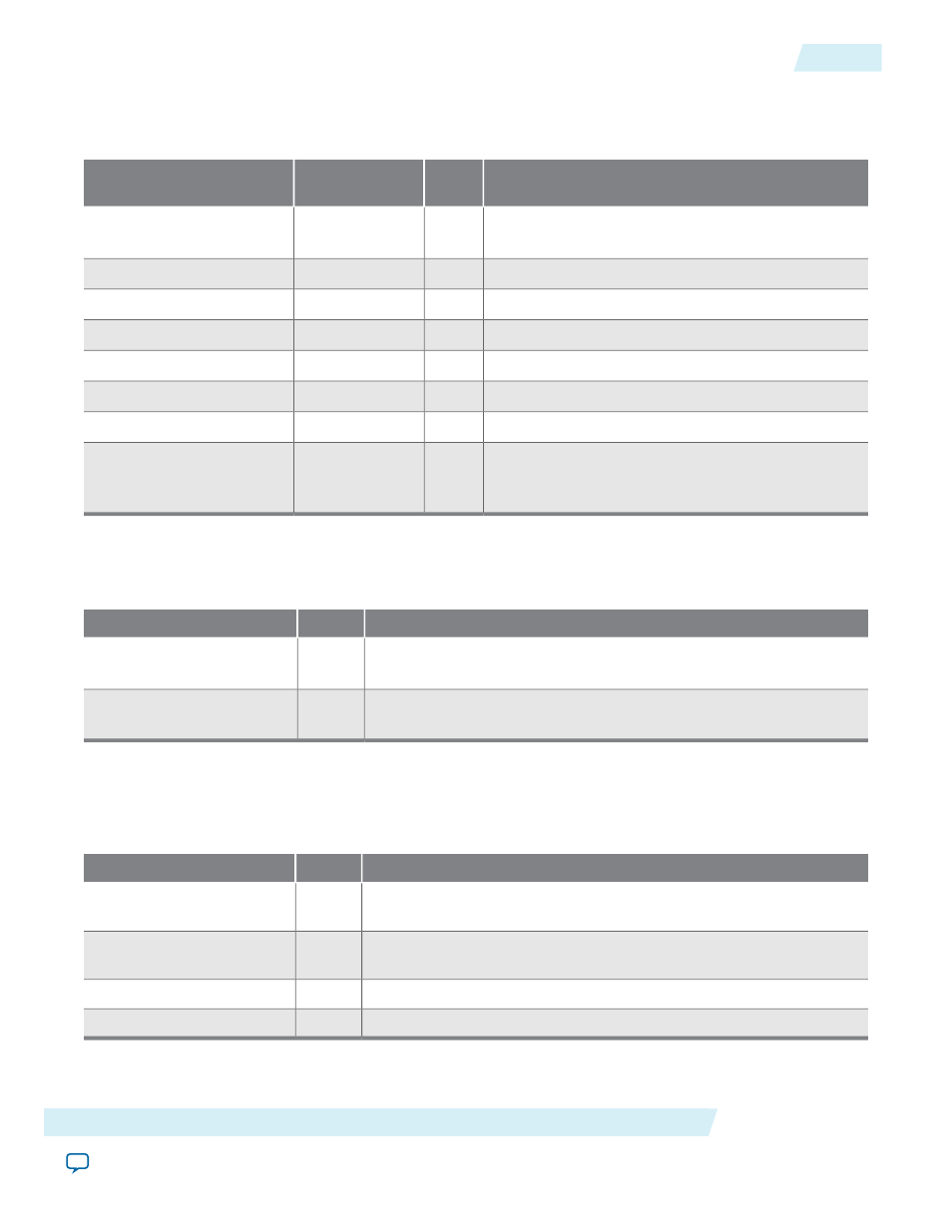
PCS Control Interface Signals
Table 7-36: Register Interface Signals
Description
I/O
Avalon-MM Signal
Type
Name
Register access reference clock. Set the signal to a
value less than or equal to 125-MHz.
I
clk
reg_clk
Active-high reset signal for
reg_clk
clock domain.
I
reset
reset_reg_clk
Register write enable.
I
write
reg_wr
Register read enable.
I
read
reg_rd
16-bit word-aligned register address.
I
address
reg_addr[4:0]
Register write data. Bit 0 is the least significant bit.
I
writedata
reg_data_in[15:0]
Register read data. Bit 0 is the least significant bit.
O
readdata
reg_data_out[15:0]
Register interface busy. Asserted during register read
or register write. A value of 0 indicates that the read
or write is complete.
O
waitrequest
reg_busy
PCS Reset Signals
Table 7-37: Reset Signals
Description
I/O
Name
Active-high reset signal for PCS
rx_clk
clock domain. Assert this
signal to reset the logic synchronized by
rx_clk
.
I
reset_rx_clk
Active-high reset signal for PCS
tx_clk
clock domain. Assert this
signal to reset the logic synchronized by
tx_clk
.
I
reset_tx_clk
MII/GMII Clocks and Clock Enablers
Data transfers on the MII/GMII interface are synchronous to the receive and transmit clocks.
Table 7-38: MAC Clock Signals
Description
I/O
Name
Receive clock. This clock is derived from the TBI clock
tbi_rx_clk
and set to 125 MHz.
O
rx_clk
Transmit clock. This clock is derived from the TBI clock
tbi_tx_clk
and set to 125 MHz.
O
tx_clk
Receive clock enabler. In SGMII mode, this signal enables
rx_clk
.
O
rx_clkena
Transmit clock enabler. In SGMII mode, this signal enables
tx_clk
.
O
tx_clkena
Altera Corporation
Interface Signals
7-35
PCS Control Interface Signals
UG-01008
2014.06.30