4 up/down count pwm output operation, 9 .1 .4 up/down count pwm output operation -5, Figure 9-3 – Maxim Integrated MAX31782 User Manual
Page 86: 4up/downcountpwmoutputoperation
MaximIntegrated 9-5
MAX31782 User’s Guide
Revision 0; 8/11
9.1.4Up/DownCountPWMOutputOperation
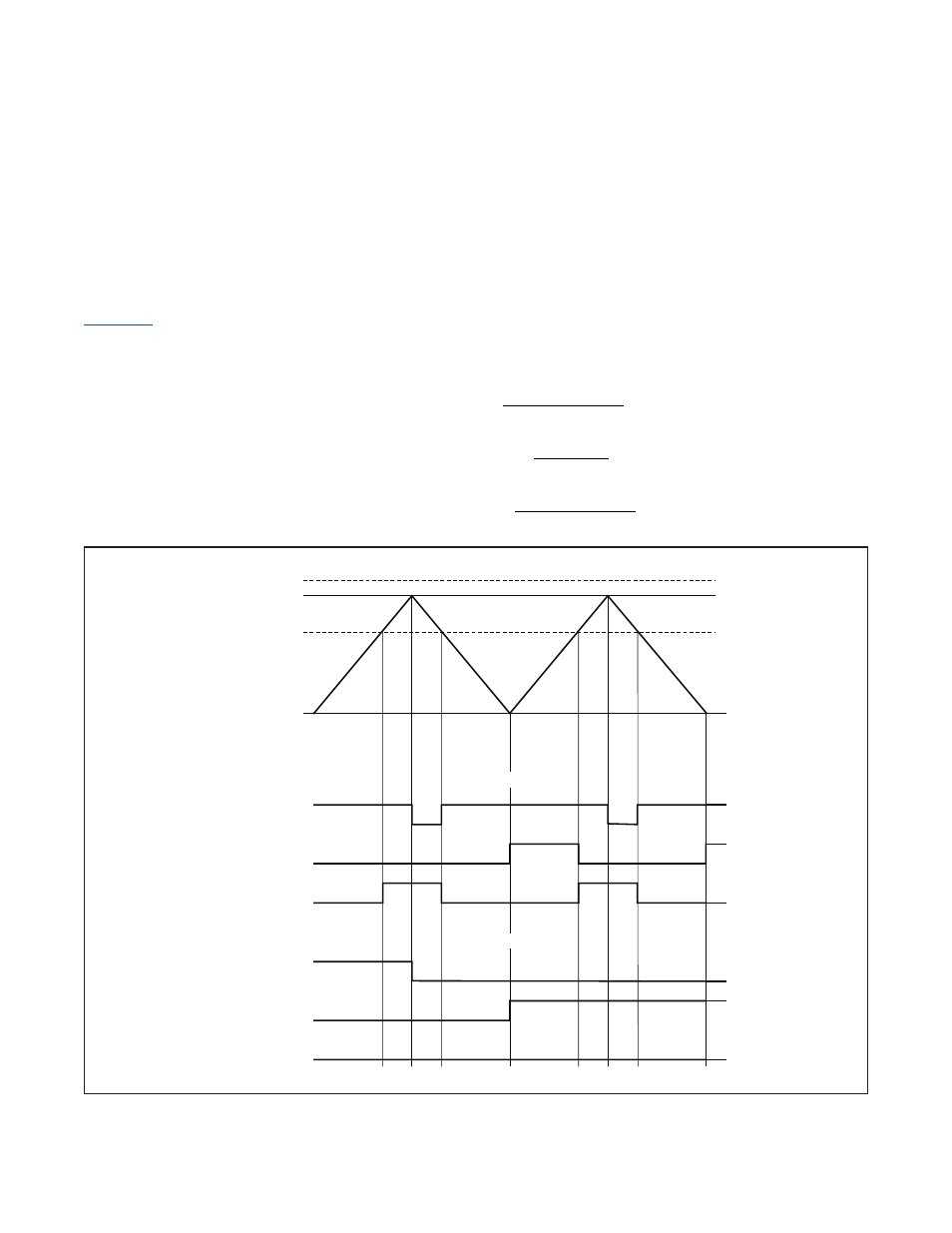
The PWM can also operate in an up/down count configuration by setting DCEN = 1 . The value in PWMVn counts upward
until it reaches the value in the reload register (PWMRn) . On the next cycle the count reverses direction and starts count-
ing down . When PWMVn reaches 0000h, the count again reverses direction and begins counting up .
When operating in an up/down count configuration and either set or reset mode, the PWM effectively allows 17-bit
resolution . In set mode the duty cycle is always less than 50%, and in reset mode the duty cycle is always greater than
50% . The toggle mode provides a center-aligned 16-bit PWM with twice the period of the normal PWM output mode .
illustrates the PWM waveforms when operating in up/down count PWM output mode . The up/down count
PWM output period and duty cycle are calculated as follows:
Period = 2
× PWMRn × PWM .n CLOCK PERIOD
Duty Cycle in Set Mode =
PWMRn PWMCn
2 PWMRn
+
×
Duty Cycle in Reset Mode =
PWMCn
2 PWMRn
×
Duty Cycle in Toggle Mode =
PWMRn PWMCn
PWMRn
−
Figure 9-3. PWM Waveform in Up/Down Count PWM Output Mode
PWMCn > PWMRn
PWMCn < PWMRn
0000h
SET MODE
RESET MODE
TOGGLE MODE
SET MODE
RESET MODE
TOGGLE MODE
PWMRn
PWMCn < PWMRn
PWMCn > PWMRn
PWMVn