8 clock stretching, 7 .1 .8 clock stretching -6, Figure 7-3 . slave i – Maxim Integrated MAX31782 User Manual
Page 62: C clock stretching -6, 8clockstretching
MaximIntegrated 7-6
MAX31782 User’s Guide
Revision 0; 8/11
7.1.8ClockStretching
If a slave device cannot receive or transmit another complete byte of data, it can hold SCL low, forcing the master to
wait . Data transfer continues when the slave is ready for another byte of data and releases SCL .
The I
2
C slave controller can hold SCL low at the completion of each byte being transferred . If the I
2
C clock stretch
enable bit (I2CSTREN) is set to a 1, the I
2
C controller holds SCL low after the clock pulse defined by the I
2
C clock
stretch select bit (I2CSTRS) . If I2CSTRS = 0, the I
2
C controller holds SCL low after the falling edge of the 9th clock pulse .
Otherwise, if I2CSTRS = 1, the I
2
C controller holds SCL low after the falling edge of the 8th clock pulse . When the I
2
C
controller is holding SCL low, the I
2
C clock stretch interrupt bit (I2CSTRI) is set . The I
2
C slave controller holds SCL low
until I2CSTRI is cleared to 0 by software .
2
C slave controller clock stretching after receiving the
9th clock of a byte .
Normally when the I
2
C slave controller is receiving data, the value of I2CACK is output after the 8th clock falling edge .
However, if clock stretching is enabled after the 8th clock, the I
2
C slave controller continually outputs the I2CACK
bit until clock stretching is released by software . This allows software time to inspect data that was received before
responding with an appropriate acknowledge bit .
Most applications that use the MAX31782’s I
2
C slave controller need to use clock stretching . Generally the application
is set to only respond to interrupts from the I
2
C slave controller, therefore it does not have to continuously poll the slave
I
2
C controller . After each byte transfer is complete, the I
2
C slave controller needs to either read the received byte from
I2CBUF_S or write the next byte to transmit to I2CBUF_S . Without using clock stretching, the host can begin clocking the
next byte before the I
2
C slave controller is prepared . A few conditions that can require clock stretching to be enabled
are listed below .
• When a slave address match is made and the R/W bit is set, the I
2
C slave controller is expected to transmit a byte
of data to the host . This byte of data needs to be written to I2CBUF_S after the 8th clock of the slave address (when
I2CBUSY is cleared) and prior to the first clock of the data byte . If clock stretching is not used, software may not be
able to write the correct data into I2CBUF_S prior to the first clock of the data byte .
• Following the transmission of one byte of data to the host, another byte may be requested by the host sending an
ACK bit . The I
2
C slave controller has between the 9th clock of the first data byte (when I2CBUSY is cleared) and the
first clock of the second byte to write to I2CBUF_S . If clock stretching is not used, software may not be able to write
the next byte to I2CBUF_S prior to the first clock of the second byte .
• After a byte is received by the I
2
C slave controller it may be necessary to stretch the clock . This allows software time
to read the byte from I2CBUF_S and do any data processing . Without using clock stretching, there is a chance that
a second byte could be sent prior to the software reading the first byte, creating a receive overrun condition . Any
additional data that is sent after this time is lost .
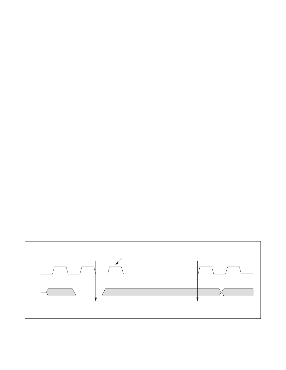
Figure 7-3. Slave I
2
C Clock Stretching
SCL
SDA
LAST 2 SCL CYCLES OF 1ST BYTE
FIRST 2 SCL CYCLES OF 2ND BYTE
FIRMWARE CAN PROCESS I
2
C DATA WHILE SCL IS HELD LOW
CLOCK STRETCHING ENABLED
AFTER THE 9TH SCL CLOCK
ACK
SLAVE HOLDS SCL LOW
I2CSTRI = 1
I2CSTRI SET TO 0
SLAVE RELEASES SCL
NORMALLY THE
MASTER OUTPUTS
SCL HIGH HERE
MASTER CONTINUES
CLOCKING SCL.
8
9
1
2