1 auto-reload mode, 12 .1 .1 auto-reload mode -3, Figure 12-1 . auto-reload mode block diagram -3 – Maxim Integrated MAX31782 User Manual
Page 105: 1auto-reloadmode
MaximIntegrated 12-3
MAX31782 User’s Guide
Revision 0; 8/11
12.1.1Auto-ReloadMode
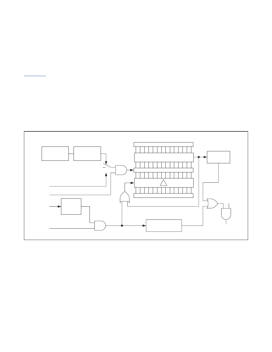
The 16-bit auto-reload mode of Timer B is established by clearing the CP/RLB bit to 0 . In this mode, the timer performs
a simple 16-bit timer or counter function that is reset to 0000h when a match between the Timer B count value register
(TB0V) and the Timer B capture/reload register (TB0R) occurs . A block diagram of auto-reload mode is illustrated in
. If the C/TB bit is a logic 0, the timer’s input clock is a prescaled system clock . When C/TB is a logic 1,
pulses on the TBA pin are counted . As in all modes, counting or timing is enabled or disabled with the TRB bit .
When enabled in auto-reload mode, the Timer B begins counting up from the current value contained in the TB0V
register . When the value in the TB0V register reaches the value in the capture/reload register TB0R, the TFB flag is set
to 1, which can generate an interrupt if enabled . Also when this match is made, the timer reloads the TB0V register with
0000h and continues timing or counting from 0000h . The reload value contained in the TB0R register is preloaded by
software . The TB0R register cannot be used for the capture function while also performing auto-reload .
While in auto-reload mode, the Timer B can also be forced to reload the TB0V register with 0000h using the TBB pin . If
the EXENB bit is set to 1, a 1 to 0 transition (falling edge) on the TBB pin causes a reload . If the EXENB bit is cleared
to 0, the TBB pin is ignored .
Figure 12-1. Auto-Reload Mode Block Diagram
SYSTEM
CLOCK
CLOCK PRESCALER
TBPS[2:0]
CLK
RELOAD
TBA PIN
TRB
TBB PIN
EXENB
FALLING
EDGE
15
0
15
0
TB0R
COMPARE
TB0V
0000h
EXFB = 1
TFB = 1
ETB
TIMER B
INTERRUPT
0
1
C/TB