1 detailed description, 12 .1 detailed description -2, 1detaileddescription – Maxim Integrated MAX31782 User Manual
Page 104
MaximIntegrated 12-2
MAX31782 User’s Guide
Revision 0; 8/11
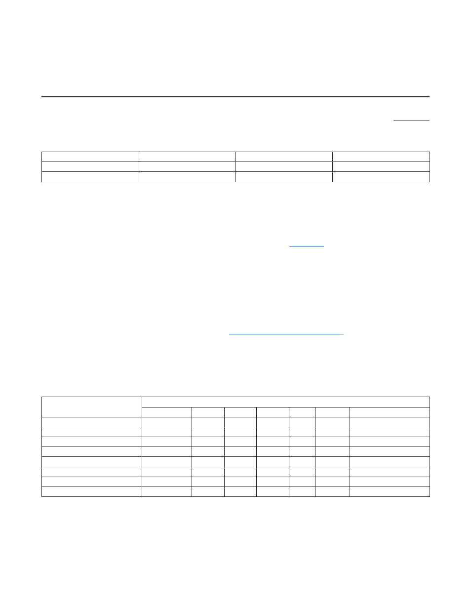
SECTION 12: TIMER B MODULE
The MAX31782 provides one Timer B module that can be configured to provide different timer, counter, clock, or PWM
functions . The Timer B uses the TBB and TBA pins, which are also used for JTAG and GPIO operation .
details these pins .
Table12-1.TimerBPins
Table12-2.TimerBModeSummary
12.1DetailedDescription
The Timer B is a 16-bit programmable module that supports input clock prescaling and set/reset/toggle PWM output
control functionality . Another distinguishing characteristic of Timer B is that its count ranges from 0000h to the value
stored in the 16-bit capture/reload register (TBR) instead of FFFFh as in some timers .
The possible Timer B operating modes and related control bits are shown in
. A complete description of each
mode is contained in the subsequent sections .
All timer operation and functionality is set using the Timer B control register, TB0CN . Three other registers are used to
hold the current timer/counter value (TB0V), the capture/reload value (TB0R), and a compare value (TB0C) .
In all modes of operation, the timer is enabled by setting the Timer B run control bit (TRB) in the Timer B control register
to 1 . If this bit is cleared to 0 (reset default condition), no timer activity is possible .
When the Timer B is operated as a timer (i .e ., it counts scaled system clocks), the TBPS[2:0] bits in the timer control
register determine the factor by which the active system clock is divided (prescaled) before being counted by the timer .
Other relevant control bits are described in the following mode descriptions . A complete listing of the Timer B registers
and bits with their effects on timer operation are given in
12.2 Timer B Register Descriptions
.
The Timer B pins, TBA and TBB, are used for GPIO and JTAG, respectively, by default . The Timer B functionality of
these pins is enabled through the TB0CN register . The following sections detail the TB0CN configurations required
depending on the desired Timer B function . To use the TBB pin, the JTAG port must also be disabled by setting the
TAP bit in the SC register to 0 .
TIMERBPIN
MAX31782PINNUMBER
GPIOPIN
JTAGPIN
TBA
33
P6 .4
—
TBB
35
P6 .2
TMS
TIMERBOPERATIONAL
MODE
TB0CNREGISTERBITSETTINGS
TBCS:TBCR
TBOE
DCEN
EXENB
C/TB
CP/RLB
OPTIONALCONTROL
Auto-Reload
00
0
0
0
X
0
Auto-Reload Using TBB Pin
00
0
0
1
X
0
Capture Using TBB Pin
00
0
0
1
X
1
Up/Down Count Using TBB Pin
00
0
1
0
X
0
Up-Count PWM/Output Control
≠00
X
0
X
X
0
Up/Down PWM/Output Control
≠00
X
1
X
X
0
—
—
0
X
X
1
X
Input Clock = TBA Pin
Clock Output on TBA Pin
—
1
X
X
0
0