3 normal pwm output operation, 9 .1 .3 normal pwm output operation -4, Figure 9-2 – Maxim Integrated MAX31782 User Manual
Page 85: 3normalpwmoutputoperation
MaximIntegrated 9-4
MAX31782 User’s Guide
Revision 0; 8/11
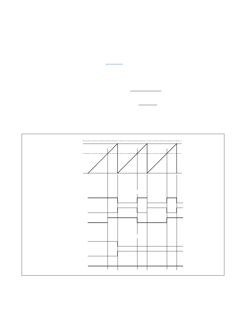
Figure 9-2. PWM Output Waveform in Normal PWM Output Mode
9.1.3NormalPWMOutputOperation
When operating in PWM output mode and configured for up count (DCEN = 0), the value in PWMVn is incremented until
it reaches the reload value, PWMRn . At this point, PWMVn reloads with 0000h, the TFB flag is set (which can generate
an interrupt if enabled), and counting continues .
illustrates the PWM waveforms when the PWM is operating
with DCEN = 0 . The period of the PWM waveform is set by the value in the PWMRn register . The set and reset modes
provide similar functionality . The formulas for period and duty cycle are:
PWM PERIOD = (PWMRn + 1)
× PWM .n CLOCK PERIOD
Duty Cycle in Set Mode =
PWMRn PWMCn
PWMRn 1
−
+
Duty Cycle in Reset Mode =
PWMCn
PWMRn 1
+
The toggle mode generates a 50% duty-cycle waveform if the PWMCn register remains fixed . The period of the wave-
form is:
PERIOD = 2
× (PWMRn + 1) × PWM .n CLOCK PERIOD
PWMCn > PWMRn
PWMCn < PWMRn
0000
PWMVn
SET MODE
RESET MODE
TOGGLE MODE
SET MODE
RESET MODE
TOGGLE MODE
PWMRn
PWMCn < PWMRn
PWMCn > PWMRn