2 i2c slave controller register descriptions, 1 i2c slave control register (i2ccn_s), 7 .2 i – Maxim Integrated MAX31782 User Manual
Page 64: C slave controller register descriptions -8, 7 .2 .1 i, C slave control register (i2ccn_s) -8, Cslavecontrollerregisterdescriptions, Cslavecontrolregister(i2ccn�s)
MaximIntegrated 7-8
MAX31782 User’s Guide
Revision 0; 8/11
7.2I
2
CSlaveControllerRegisterDescriptions
The following registers are used to control the I
2
C slave interface, which uses the SDA and SCL pins . These registers
control the I
2
C slave interface if it is operating as either a slave or master . The bit descriptions detail how to use these
registers when operating in slave mode . When operating in master mode, some of the bits and registers have different
functionality . See
section for more information on how to control the I
2
C
slave interface when it is operating as a master .
7.2.1I
2
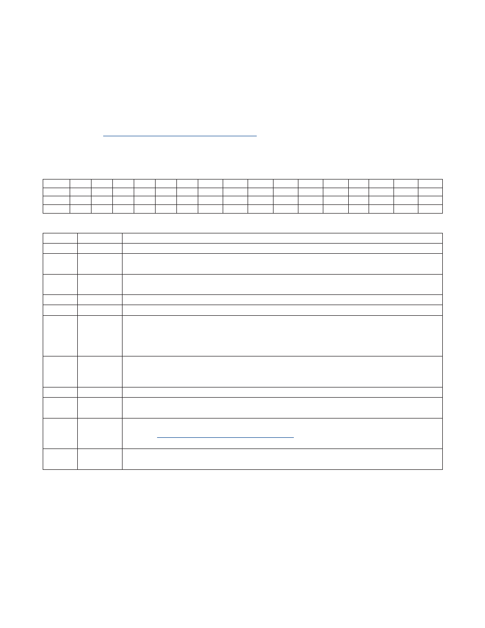
CSlaveControlRegister(I2CCN�S)
Address: M2[0Ch]
*Unrestricted read. Unrestricted write access when I2CBUSY = 0. Writes to I2CEN are disabled when I2CBUSY = 1.
Bit
15
14
13
12
11
10
9
8
7
6
5
4
3
2
1
0
Name
—
—
—
—
—
—
I2CSTREN I2CGCEN I2CSTOP I2CSTART I2CACK
I2CSTRS
—
I2CMODE I2CMST
I2CEN
Reset
0
0
0
0
0
0
0
0
0
0
0
0
0
0
0
1
Access
r
r
r
r
r
r
rw*
rw*
r
r
rw*
rw*
r
r
r
rw*
BIT
NAME
DESCRIPTION
15:10
—
Reserved . The user should not write to these bits .
9
I2CSTREN
I
2
C Slave Clock Stretch Enable . Setting this bit to 1 stretches the clock (holds SCL low) at the end of
the clock cycle specified in I2CSTRS . Clearing this bit disables clock stretching .
8
I2CGCEN
I
2
C Slave General Call Enable . Setting this bit to 1 enables the I
2
C to respond to a general call
address (address = 0000 0000) . Clearing this bit to 0 disables the response to general call address .
7
I2CSTOP
This bit has no function when operating in slave mode .
6
I2CSTART
This bit has no function when operating in slave mode .
5
I2CACK
I
2
C Slave Data Acknowledge Bit . This bit selects the acknowledge bit returned by the I
2
C controller
while acting as a receiver . Setting this bit to 1 generates a NACK (leaving SDA high) . Clearing the
I2CACK bit to 0 generates an ACK (pulling SDA low) during the acknowledgement cycle . This bit
retains its value unless changed by software or hardware .
4
I2CSTRS
I
2
C Slave Clock Stretch Select . Setting this bit to 1 enables clock stretching after the falling edge of
the 8th clock cycle . Clearing this bit to 0 enables clock stretching after the falling edge of the 9th clock
cycle . This bit has no effect when clock stretching is disabled (I2CSTREN = 0) .
3
—
Reserved . The user should not write to this bit .
2
I2CMODE
I
2
C Slave Transfer Mode Select . This bit reflects the actual R/W bit value in the current I
2
C transfer
and is set by hardware . Software writing to this bit is ignored .
1
I2CMST
I
2
C Master Mode Enable . Setting this bit to 1 enables I
2
C master functionality on the SDA and SCL
pins . See
for more details . Setting this bit to 0 enables
I
2
C slave functionality .
0
I2CEN
I
2
C Slave Enable . This bit enables the I
2
C slave function . When set to 1, I
2
C slave communication is
enabled . When cleared to 0, the I
2
C function is disabled .