3 memory types, 1 flash memory, 2 .3 memory types -4 – Maxim Integrated MAX31782 User Manual
Page 8: 2 .3 .1 flash memory -4
MaximIntegrated 2-4
MAX31782 User’s Guide
Revision 0; 8/11
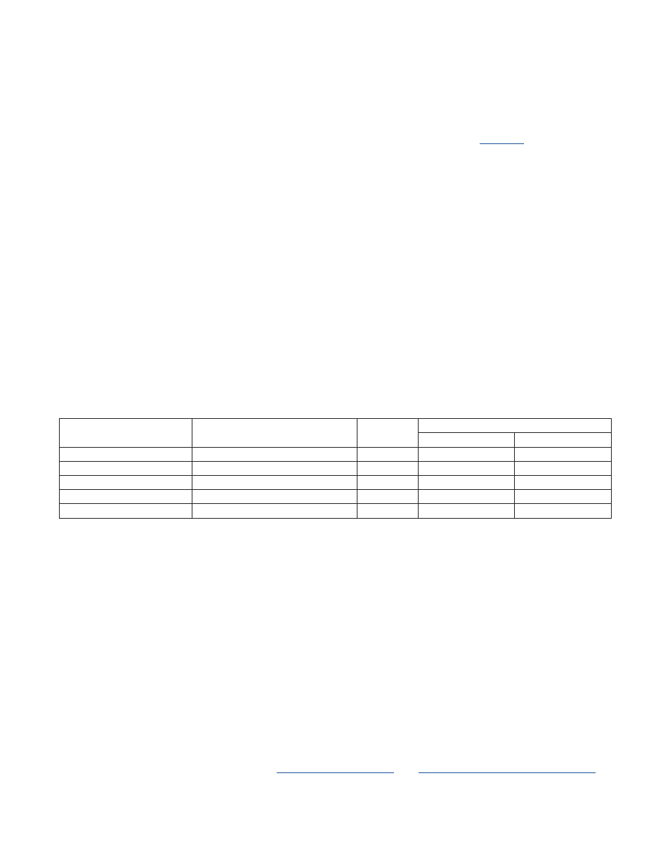
Registers can be 8 or 16 bits in length . Some registers can contain reserved bits . The user should not write to any
reserved bits . Data transfers between registers of different sizes are handled as shown in
.
• If the source and destination registers are both 8 bits wide, data is copied bit to bit .
• If the source register is 8 bits wide and the destination register is 16 bits wide, the data from the source register is
transferred into the lower 8 bits of the destination register . The upper 8 bits of the destination register are set to the
current value of the PFX register; this value is normally zero, but it can be set to a different value by the previous
instruction if needed . The PFX register reverts back to zero after one cycle, so this must be done by the instruction
immediately before the one that is using the value .
• If the source register is 16 bits wide and the destination register is 8 bits wide, the lower 8 bits of the source are
transferred to the destination register .
• If both registers are 16 bits wide, data is copied bit to bit .
The above rules apply to all data movements between defined registers . Data transfer to/from undefined register loca-
tions has the following behavior:
• If the destination is an undefined register, the MOVE is a dummy operation but can trigger an underlying operation
according to the source register (e .g ., @DPn--) .
• If the destination is a defined register and the source is undefined, the source data for the transfer depends upon
the source module width . If the source is from a module containing 8-bit or 8-bit and 16-bit source registers, the
source data is equal to the prefix data as the upper 8 bits and 00h as the lower 8 bits . If the source is from a module
containing only 16-bit source registers, 0000h source data is used for the transfer .
Table2-1.Register-to-RegisterTransferOperations
2.3MemoryTypes
In addition to the internal register space, the MAX31782 incorporates the following memory types:
• 32KWords of flash memory
• 1KWords of SRAM
• 4KWords of utility ROM contain a debugger and program loader
• 16-level stack memory for storage of program return addresses and general-purpose use
The memory on the MAX31782 is organized according to a Harvard architecture . This means that there are separate bus-
ses for both program and data memory . Stack memory is also separate and is accessed through a dedicated register set .
2.3.1FlashMemory
The MAX31782 contains 32KWords (32K x 16) of flash memory . The flash memory begins at address 0000h and is
contiguous through word address 7FFFh . The flash memory can also be used for storing lookup tables and other non-
volatile data .
The incorporation of flash memory allows the contents of the flash memory to be upgraded in the field, either by the
application or by one of the bootloaders (JTAG or I
2
C) . Writing to flash memory must be done indirectly by using rou-
tines that are provided by the utility ROM . See
and
SECTION 18: In-System Programming
for
more details .
SOURCEREGISTERSIZE
(BITS)
DESTINATIONREGISTERSIZE
(BITS)
PREFIX
SET?
DESTINATIONSETTOVALUE
HIGH8BITS
LOW8BITS
8
8
X
—
Source [7:0]
8
16
No
00h
Source [7:0]
8
16
Yes
PFX [7:0]
Source [7:0]
16
8
X
—
Source [7:0]
16
16
X
Source [15:8]
Source [7:0]