2 frame pointer, 4 data memory mapping, 2 .4 .3 .2 frame pointer -8 – Maxim Integrated MAX31782 User Manual
Page 12: 2 .4 .4 data memory mapping -8
MaximIntegrated 2-8
MAX31782 User’s Guide
Revision 0; 8/11
2.4.3.2FramePointer
The frame pointer (BP[OFFS]) is formed by the 16-bit unsigned addition of the 16-bit frame pointer base register (BP)
and the 8-bit frame pointer offset register (OFFS) . The method the MAX31782 uses to access data using the frame
pointer is similar to the data pointers . When increments or decrements are used, only the value of OFFS is incremented
or decremented . The base pointer (BP) remains unaffected by increments or decrements of the OFFS register, includ-
ing when the OFFS register rolls over from FFh to 00h or from 00h to FFh . Following are examples of how to use the
frame pointer .
move BP, #0100h
; set base pointer to address 100h
move OFFS, #10h
; set the offset to 10h,
move Acc, @BP[OFFS]
; read data from location 0110h
move @BP[OFFS], Acc
; write data to location 0110h
move Acc, @BP[OFFS++]
; increment OFFS after read
move Acc, @BP[OFFS++]
; decrement OFFS after read
move @BP[++OFFS], Acc
; increment OFFS before write
move @BP[--OFFS], Acc
; decrement OFFS before write
2.4.4DataMemoryMapping
The MAX31782’s pseudo-Von Neumann memory map allows the MMU to read data from each of the three memory seg-
ments (flash, SRAM, utility ROM) . The MMU can also write data directly to the SRAM memory segment . Data memory
can be written to the flash memory segment, but because writing to flash requires the use of the utility ROM routines,
this is not a direct access . The logical mapping of the three memory segments as data memory varies depending upon:
• from which memory segment instructions are currently being executed
• if data memory is being accessed in word or byte mode
In all cases, whichever memory segment is currently being used as program memory cannot be accessed as data
memory .
When the program is currently executing instructions from either the SRAM or utility ROM memory segments, the flash
memory is mapped to half the data memory space . If word access mode is selected, both pages (32KWords) can
be logically mapped to data memory space . If byte access mode is selected, only one page (32KB) can be logically
mapped to half of the data memory space . When operating in byte access mode, the selection of which flash page is
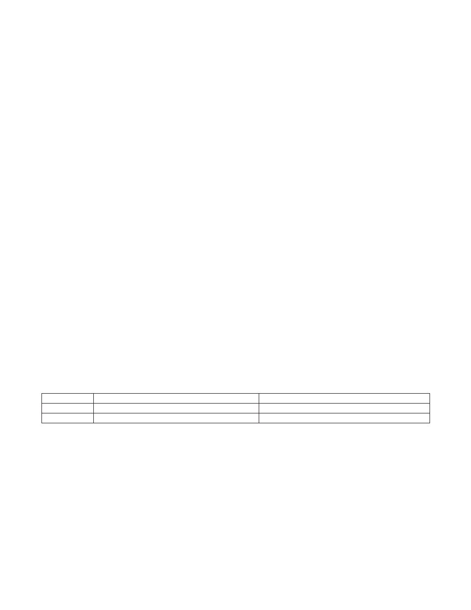
mapped into data memory space is determined by the code data access bit (CDA0):
The next three sections detail the mapping of the different memory segments as data memory depending upon from
which memory segment instructions are currently being executed .
CDA0
SELECTEDPAGEINBYTEMODE
SELECTEDPAGEINWORDMODE
0
P0
P0 and P1
1
P1
P0 and P1