1 tap controller, 16 .1 tap controller -3, Figure 16-2 . tap controller state diagram -3 – Maxim Integrated MAX31782 User Manual
Page 131: 1tapcontroller
MaximIntegrated 16-3
MAX31782 User’s Guide
Revision 0; 8/11
16.1TAPController
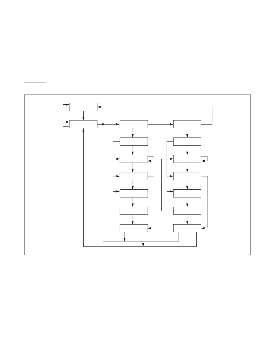
The TAP controller is a synchronous state machine that responds to changes at the TMS and TCK signals . Based on its
state transition, the controller provides the clock and control sequence for TAP operation . The performance of the TAP
is dependent on the TCK clock frequency . The maximum TCK clock frequency should be limited to 1/8 the system clock
frequency . This section provides a brief description of the state machine and its state transitions . The state diagram in
summarizes the transitions caused by the TMS signal sampling on the rising edge at TCK . The TMS signal
value is presented adjacent to each state transition in the figure .
Figure 16-2. TAP Controller State Diagram
TEST-LOGIC-RESET
RUN-TEST-IDLE
SELECT-DR-SCAN
EXIT2-DR
CAPTURE-DR
SHIFT-DR
EXIT1-DR
PAUSE-DR
UPDATE-DR
SELECT-IR-SCAN
EXIT2-IR
CAPTURE-IR
SHIFT-IR
EXIT1-IR
PAUSE-IR
UPDATE-IR
1
0
1
1
1
1
1
1
1
1
1
1
1
1
1
0
0
0
0
0
0
0
0
0
0
0
0
0
1
1
0
0
- DS80C390 (58 pages)
- DS5001FP (26 pages)
- MAX1416 (14 pages)
- MAX5865 (18 pages)
- DS33Z41 (167 pages)
- MAX1202 (7 pages)
- USBTO232 (31 pages)
- HFAN-09.5.0: Pattern Creator/Converter Software (8 pages)
- MAX-IDE MAXQ Microcontrollers (11 pages)
- MAX6876 Power-Supply Tracker/Sequencer (6 pages)
- MAX6877 Power-Supply Tracker/Sequencer (3 pages)
- 78Q8430 ARM9(920T) Linux Driver Diagnostic Guide (19 pages)
- 78Q8430 Software Driver (54 pages)
- 78Q8430 ST 5100/OS-20 with NexGen TCP/IP Stack (28 pages)
- 6612_OMU_S2_URT_V1_13 (56 pages)
- 6612_OMU_S2+2_URT_V1_14 (58 pages)
- 71M6511 Power Meter IC Family Software (137 pages)
- 71M65xx ADM51 ICE Safety Notice (2 pages)
- 71M6511 2-Layer Demo Board (2 pages)
- 71M6511 4-Layer Demo Board (2 pages)
- 78Q8430 Linux Driver ARM Platform (22 pages)
- 71M6513 Demo Board (2 pages)
- 71M6521DE Energy Meter IC Family Software (138 pages)
- 71M6521 Demo Board (2 pages)
- 71M6531 Demo Board (2 pages)
- 71M6531 Energy Meter IC Family Software (116 pages)
- 71M6533 Demo Board (2 pages)
- 71M6534H Demo Board (2 pages)
- 71M6515H Demo Board (2 pages)
- 73S1209F Evaluation Board (2 pages)
- 73S12xxF (38 pages)
- 73S12xxF Software (93 pages)
- 73S1210F Evaluation Board Lite (2 pages)
- 73S1210F Evaluation Board (2 pages)
- 73S1210F Multi-SAM Evaluation Board Lite (2 pages)
- 73S12xxF USB-CCID Linux DFU Host Application (8 pages)
- 73S1215F Device Firmware Upgrade Host Driver/Application (10 pages)
- 73S12xxF USB-CCID Host GUI (22 pages)
- 73S1215F Windows XP 32 USB CCID and DFU Drivers (15 pages)
- 73S1215F CCID USB Linux Driver (16 pages)
- 73S1215F Evaluation Board (2 pages)
- 73S1215F Evaluation Board Lite (2 pages)
- 73S1217F Evaluation Board (2 pages)
- 73S1217F Evaluation Board Lite (2 pages)
- MAXQ Family (216 pages)