1 detailed description, 1 conversion modes, 6 .1 detailed description -2 – Maxim Integrated MAX31782 User Manual
Page 45: 6 .1 .1 conversion modes -2, Figure 6-1 . adc functional block diagram -2, 1detaileddescription, 1conversionmodes
MaximIntegrated 6-2
MAX31782 User’s Guide
Revision 0; 8/11
SECTION 6: ANALOG-TO-DIGITAL CONVERTER (ADC)
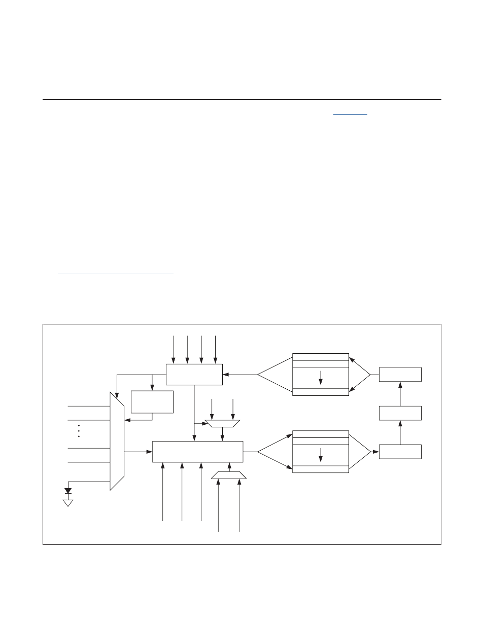
The MAX31782 contains a 12-bit analog-to-digital converter (ADC) with a 7-input mux (
) . The mux selects the
ADC input from six external channels and one internal channel . The six external channels can operate in fully differen-
tial voltage mode or in single-ended voltage mode . In addition, any of the six external channels can be configured to
measure the temperature of an external diode . The internal channel is used exclusively to measure the die temperature .
6.1DetailedDescription
6.1.1ConversionModes
The ADC in the MAX31782 can operate in three modes, which are selected using the EXTEMP and ADCH bits in the
configuration register:
1) Voltage Conversion Mode
2) External Temperature Sensing Mode
3) Internal Temperature Sensing Mode
In voltage conversion mode (EXTEMP = 0) and ADCH
≠ 6 or 7, the ADC reference can be either internal (IREFEN = 1)
or external (IREFEN = 0) . If the internal reference is used, the ADC full scale can be set to either 1 .225V (ADGAIN = 0)
or 5 .5V (ADGAIN = 1) . When an external reference is desired, the reference supply needs to be connected to pin AD3N .
See
6.1.6 Using an External Reference
for more information about using an external reference .
When external temperature sensing mode is selected, current is forced into an external diode that is connected
between the user specified channel pins (set by ADCH[2:0]) . The diode voltage is converted into a digital value that
gives the temperature value . The ADC automatically uses the internal reference when performing a temperature conver-
sion . Whenever ADCH[2:0] = 6 or 7, internal temperature sensing mode is enabled and EXTEMP has no effect .
Figure 6-1. ADC Functional Block Diagram
ADC
SEQUENCER
CONFIGURATION[0]
DATA BUFFER[15]
DATA BUFFER[1]
DATA BUFFER[0]
ADCFG = 1
ADIDX[2:0]
ADCFG = 0
ADIDX[3:0]
ADDATA
CONFIGURATION[7]
CONFIGURATION[1]
ADSTART
ADEND
ADCONV
ADCONT
ADCG1
ADGAIN
CURRENT SOURCE
EXTEMP = 1 OR
ADCH = 6 OR 7
MUX
12-BIT ADC CORE
VOLTAGE OFFSET (ADVOFF)
TEMPERATURE OFFSET (TOEX)
TEMPERATURE SCALE (ETS)
INTERNAL REFERENCE
EXTERNAL REFERENCE
AD0P
AD0N
AD5P
AD5N
ADCH = 6 OR 7
INTERNAL
CHANNEL
ADCG5