2 timer b register descriptions, 1 timer b control register (tb0cn), 12 .2 timer b register descriptions -10 – Maxim Integrated MAX31782 User Manual
Page 112: 12 .2 .1 timer b control register (tb0cn) -10, 2timerbregisterdescriptions, 1timerbcontrolregister(tb0cn)
MaximIntegrated 12-10
MAX31782 User’s Guide
Revision 0; 8/11
12.2TimerBRegisterDescriptions
The following peripheral registers are used to control the Timer B timer and counter functions . Addresses of registers
are given as “Mx[yy],” where x is the module number (from 0 to 5 decimal) and yy is the register index (from 00h to
1Fh hexadecimal) .
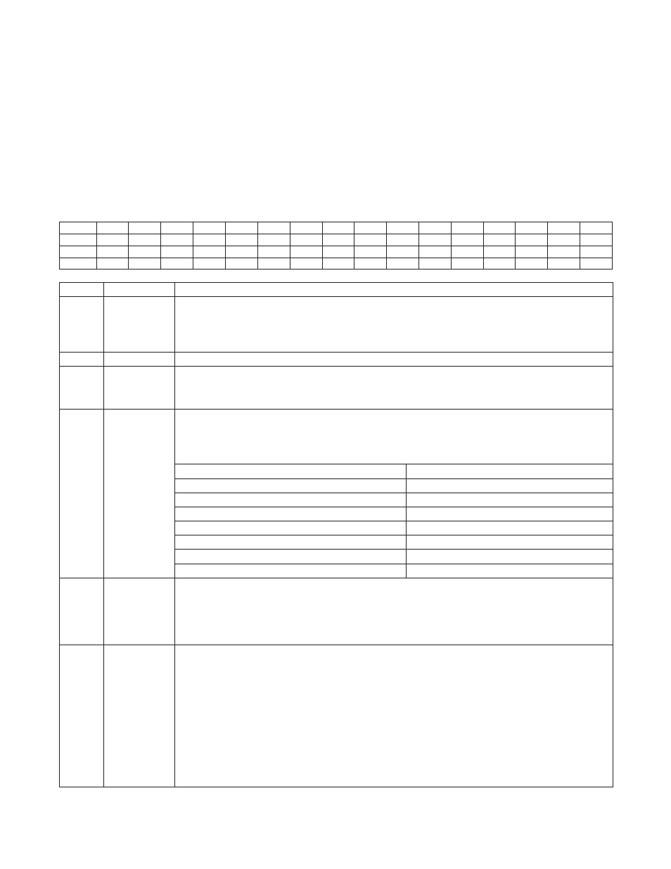
12.2.1TimerBControlRegister(TB0CN)
Register Address: M0[0Dh]
Bit
15
14
13
12
11
10
9
8
7
6
5
4
3
2
1
0
Name
C/TB
—
—
TBCS
TBCR
TBPS2
TBPS1
TBPS0
TFB
EXFB
TBOE
DCEN
EXENB
TRB
ETB
CP/RLB
Reset
0
0
0
0
0
0
0
0
0
0
0
0
0
0
0
0
Access
rw
rw
rw
rw
rw
rw
rw
rw
rw
rw
rw
rw
rw
rw
rw
rw
BIT
NAME
DESCRIPTION
15
C/TB
Counter/Timer Select . This bit determines whether Timer B functions as a timer or counter . Setting
this bit to 1 configures the Timer B to count negative transitions on the TBA pin . Clearing this bit to 0
configures the Timer B to function as a timer . The speed of the Timer B when operating as a timer is
determined by the TBPS[2:0] bits .
14:13
—
Reserved . The user should not write to these bits .
12:11
TBCS, TBCR
TBB Pin Output Set/Reset Mode Bits . These mode bits define whether the PWM mode output function
is enabled on the TBB pin and what compare mode output function is in effect . Note that the TBB pin
still has certain input functionality when the PWM output function is enabled .
10:8
TBPS[2:0]
Timer B Clock Prescaler Bits . These bits select the clock prescaler applied to the system clock,
which is then used as the Timer B clock . The TBPS[2:0] bits should be configured by the user when
the timer is stopped (TRB = 0) . While hardware does not prevent changing the TBPS[2:0] bits when
the timer is running, the resultant behavior is nondeterministic .
TBPS[2:0]
TIMERINPUTCLOCK
000
Sysclk
001
Sysclk/4
010
Sysclk/16
011
Sysclk/64
100
Sysclk/256
101
Sysclk/1024
11x
Sysclk
7
TFB
Timer B Overflow Flag . This bit is set when Timer B overflows or reaches TB0R and is reloaded to
0000h . The TFB flag is also set when TB0V is equal to 0000h in down-count mode . The setting of this
flag will cause an interrupt if enabled . This flag must be cleared by software . In clock output mode
(TBOE = 1), the TFB flag is set on an overflow; however, the TBOE = 1 condition prevents this flag
from causing an interrupt when ETB = 1 .
6
EXFB
External Timer B Trigger Flag . When the Timer B is configured as a Timer (C/TB = 0) and operating in the
following modes:
• Capture Mode (CP/RLB = 1)
• Auto-Reload Mode (CP/RLB = DCEN = 0)
• PWM Mode (CP/RLB = 1 and TBCS:TBCR
≠ 00)
A negative transition on the TBB pin causes the EXFB flag to be set if EXENB = 1 . This flag is set when
a negative edge is detected, even if the Timer B is disabled (TRB = 0) . The setting of this flag causes an
interrupt if enabled . If set by a negative transition, this flag must be cleared by software . When operating
in up/down count with auto-reload (CP/RLB = 0, DCEN = 1, and TBCS:TBCR = 00), the EXFB flag toggles
whenever the Timer B overflows or underflows . Overflow/underflow condition is described in TFB bit
description . In this mode, EXFB can be used as the 17th timer bit and does not cause an interrupt .