4 adc data and configuration register (addata), 4adcdataandconfigurationregister(addata) – Maxim Integrated MAX31782 User Manual
Page 51
MaximIntegrated 6-8
MAX31782 User’s Guide
Revision 0; 8/11
6.2.4ADCDataandConfigurationRegister(ADDATA)
Register Address: M2[09h]
The ADDATA register is used to set up the ADC sequence configurations and also to read the results of the ADC con-
versions . If the ADST .ADCFG bit is set to 1, writing to ADDATA writes to one of the configuration registers . If ADST .
ADCFG is set to 0, reading from ADDATA reads one of the conversion results .
6.2.4.1ADCConfigurationRegister(ADDATAwhenADCFG=1)
When ADCFG = 1, writing to the ADDATA register writes to one of the configuration registers . The configuration register
written to is selected by the ADIDX[2:0] bits . The ADIDX[2:0] bits automatically increment after a write to ADDATA . This
allows consecutive writes of ADDATA to set up consecutive configuration registers . The configuration registers are reset
to 0 on all forms of reset and are not writable by the user .
*When ADCFG = 1, unrestricted read, but can only be written to when ADCONV = 0.
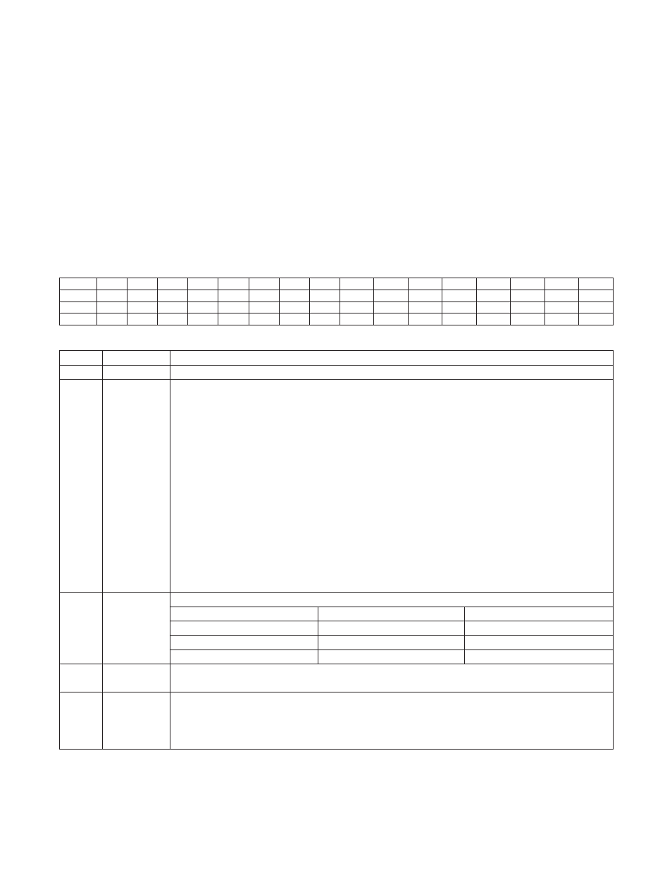
Bit
15
14
13
12
11
10
9
8
7
6
5
4
3
2
1
0
Name
—
—
—
—
—
—
—
—
EXTEMP
ADGAIN ADACQEN ADALIGN
ADDIFF
ADCH2
ADCH1
ADCH0
Reset
0
0
0
0
0
0
0
0
0
0
0
0
0
0
0
0
Access
r
r
r
r
r
r
r
r
rw*
rw*
rw*
rw*
rw*
rw*
rw*
rw*
BIT
NAME
DESCRIPTION
15:8
—
Reserved . The user should not write to these bits .
7
EXTEMP
External Temperature Mode: Setting this bit to one chooses external temperature sensing operation .
If this bit is set to zero, the ADC operates in normal voltage conversion mode for ADCH = 0–5 . For
ADCH = 6 or 7, the internal temperature is measured regardless of the setting of this bit . For external
temperature measurement, the ADC does the following:
•
A current source generated on the chip is directed to one of six positive ADC channel pins
(AD0P–AD5P) based on channel select bits described in the configuration section .
•
The current passing through the external diode is expected to return on the negative input pins
(AD0N–AD5N) of the corresponding channel .
•
The voltage across the positive and negative inputs of the channel is then scaled appropriately to
produce a temperature sample with a slope of 2 .4mV/NC .
•
The internal reference is chosen during both temperature measurement modes, external and
internal, regardless of IREFEN bit value .
•
The slope of the temperature can additionally be controlled by up to +2% in increments of ~0 .25NC
to accommodate the variance in ideality factor of the diode being used . The slope comes
preprogrammed with a 2N3904 used as a reference . The control register is at ETS (M1[16]) SFR .
•
The slope of the internal temperature sensor is not user adjustable and set at the factory .
•
The measured temperature is reported in the ADDATA register .
6
ADGAIN
ADC Reference Select . This bit selects the ADC scale factor .
IREFEN
ADGAIN
ADCSCALE
1
0
ADCG1
1
1
ADCG5
0
X
ADCG1
5
ADACQEN
ADC Acquisition Extension Enable . Setting this bit to 1 enables additional acquisition time to be insert-
ed prior to this conversion . Clearing this bit to 0 disables the extended acquisition time .
4
ADALIGN
ADC Data Alignment Select . This bit selects the ADC data alignment mode . Setting this bit to 1
returns ADC data left-aligned in ADDATA [15:3] with ADDATA[2:0] zero padded . Clearing this bit to
0 returns ADC data in right-aligned format in ADDATA[12:0] with ADDATA[15:13] sign-extended by
ADDATA[12] .