2 i2c bootloader protocol, 18 .2 .2 i, C bootloader protocol -7 – Maxim Integrated MAX31782 User Manual
Page 158: Figure 18-2 . i, C bootloader polling -7, Cbootloaderprotocol
MaximIntegrated 18-7
MAX31782 User’s Guide
Revision 0; 8/11
4) Possibly poll returned data until command execution completes .
5) Transmit 00h on TDI for each Data Out byte . Read the Data Out byte on TDO .
6) Transmit 00h on TDI and verify that the Return byte output on TDO is 3Eh .
7) The Dummy RX byte is not required for the JTAG bootloader to operate .
Some of the bootloader commands, such as the erase and CRC commands require extra time to execute . For these
commands, the two status bits can be used to verify the state of the bootloader . After issuing any of these commands,
the NOP command can continuously be sent to the bootloader . If the returned status bits are 10, the bootloader is still
busy processing the command . If the status bits are 11, the bootloader has completed execution of the command . The
first byte that was returned with status bits 11 is the first byte of valid returned data from the bootloader .
18.2.2I
2
CBootloaderProtocol
After entering the I
2
C bootloader, all I
2
C communication takes place on the default I
2
C slave address 36h . When writ-
ing data to the MAX31782, slave address 36h (R/W bit = 0) is used . To read data from the MAX31782 I
2
C bootloader,
slave address 37h (R/W bit = 1) is used . The I
2
C bootloader does not return the status bits that are available from the
JTAG bootloader . The following I
2
C steps are required to send each command
1) Send an I
2
C START, followed by writing slave address 36h (R/W bit set to write) .
2) Write command byte .
3) Write any Data In bytes .
4) The NOP byte is not required for the I
2
C interface . Sending a NOP byte when using the I
2
C bootloader places the
bootloader into an unknown state . Instead, an I
2
C restart needs to be issued, followed by writing slave address 37h
(R/W bit set to read) .
5) Possibly poll returned data until command execution completes .
6) Read and ACK all Data Out bytes .
7) Read and ACK the Return byte, verify that 3Eh was returned .
8) Read and NACK the Dummy RX byte . Ignore the returned data .
9) Send an I
2
C STOP .
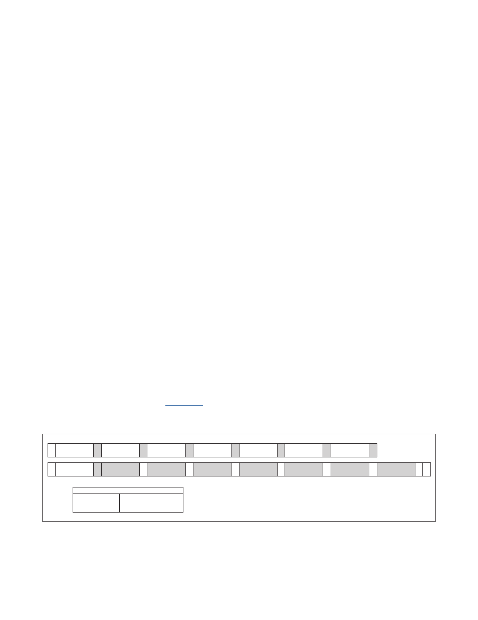
Some of the bootloader commands such as the erase and CRC commands require extra time to execute . For these
commands, the I
2
C port can be continuously polled to determine when the command completes . This polling is done
by reading the returned data bytes after sending slave address 37h . The I
2
C bootloader returns data B7h while it is
currently busy . When data other than B7h is returned, the bootloader is returning valid data . An example of polling for
the CRC Code command is shown in
. After sending slave address 37h, the I
2
C bootloader outputs B7h until
the command has finished execution . The I
2
C master needs to continue reading and returning ACK’s until a string of
four bytes with values B7h, YYh, ZZh, 3Eh is returned . The master then reads the Dummy RX byte and NACKs this byte .
Figure 18-2. I
2
C Bootloader Polling
SLAVE ADDRESS (W)
36h
COMMAND
30h
S
A
DATA IN
02h
A
Data In AddrL
00h
A
Data In AddrH
00h
A
Data In LengthL
00h
A
Data In LengthH
01h
A
A
SLAVE ADDRESS (R)
37h
POLLING
B7h
Sr
A
POLLING...
B7h
A
POLLING
B7h
A
DATA OUT CRCL
YYh
A
DATA OUT CRCH
ZZh
A
RETURN
3Eh
A
A
DUMMY RX
XX
NA P
S = START
A = ACKNOWLEDGE
Sr = REPEATED START
NA = NOT ACKNOWLEDGE
P = STOP
SHADED = SLAVE TRANSACTION
KEY