Section 13: supply voltage monitor, Section 13: supply voltage monitor -1, 1supplyvoltagemonitorregister(svm) – Maxim Integrated MAX31782 User Manual
Page 115
MaximIntegrated 13-1
MAX31782 User’s Guide
Revision 0; 8/11
SECTION 13: SUPPLY VOLTAGE MONITOR
The MAX31782 provides features to allow monitoring of its power supply . The supply voltage monitor (SVM) monitors
the V
DD
power supply and can alert the processor through an interrupt if V
DD
falls below a programmable threshold .
The MAX31782 provides the following power-monitoring features:
• SVM compares V
DD
against a programmable threshold from approximately 2 .7V to 5 .3V .
• Optional SVM interrupt can be triggered when V
DD
drops below the programmed threshold .
• SVM interrupt can be used to trigger exit from stop mode .
13.1SupplyVoltageMonitorRegister(SVM)Descriptions
The peripheral register SVM, located in Module 1, Index 9, controls the supply voltage monitor .
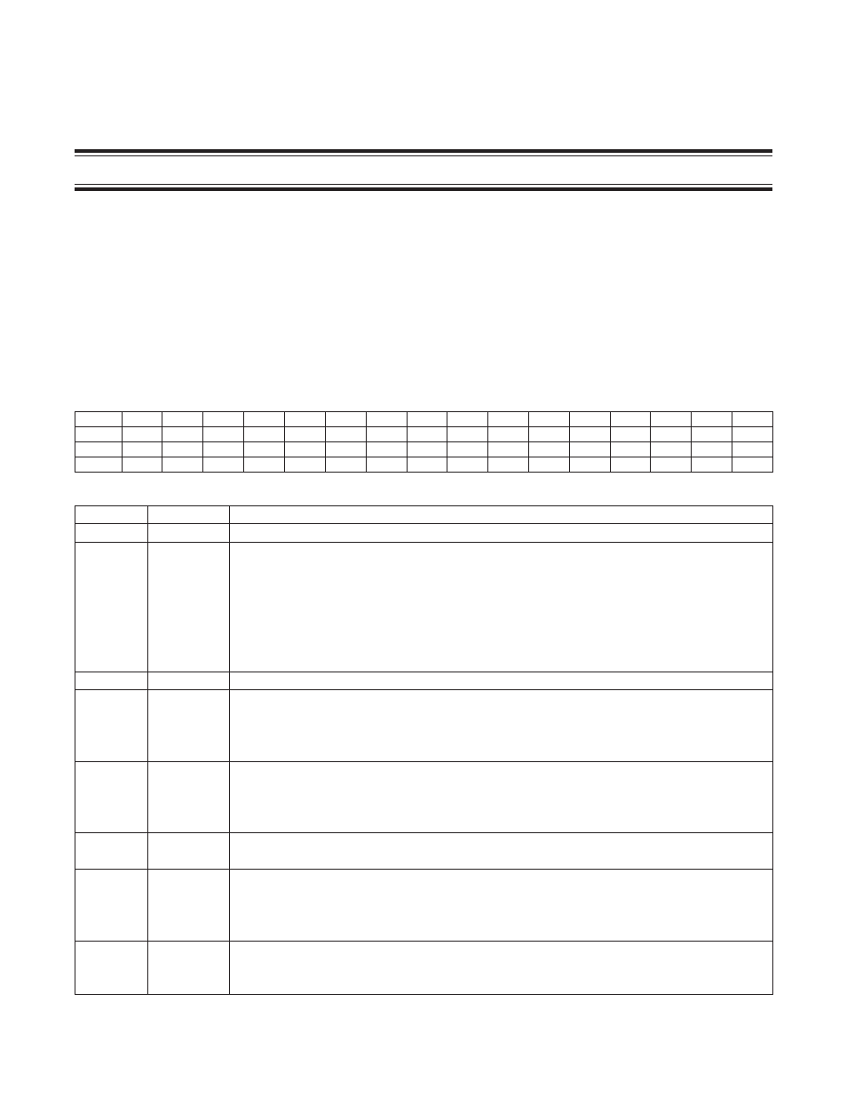
13.1.1SupplyVoltageMonitorRegister(SVM)
*SVTH[3:0] bits can only be written when the SVM is not running (SVMEN = 0).
Bit
15
14
13
12
11
10
9
8
7
6
5
4
3
2
1
0
Name
—
—
—
—
SVTH3
SVTH2
SVTH1
SVTH0
—
—
—
SVMSTOP
SVMI
SVMIE
SVMRDY SVMEN
Reset
0
0
0
0
0
0
0
0
0
0
0
0
0
0
0
0
Access
r
r
r
r
rw*
rw*
rw*
rw*
r
r
r
rw
rw
rw
r
rw
BIT
NAME
DESCRIPTION
15:12
—
Reserved . The user should not write to these bits .
11:8
SVTH[3:0]
Supply Voltage Threshold Bits [3:0] . These bits are used to select a user-defined supply voltage
threshold . If V
DD
is below this threshold, the SVMI bit is set and an interrupt can be generated if
enabled . The threshold level can be adjusted from 2 .3V to 5 .3V in 0 .2V increments . The default
value is 00h (2 .3V) .
Supply Voltage Monitor Threshold = 2 .3V + SVTH[3:0] x 0 .2V
Note that the SVTH[3:0] bits can only be modified when SVMEN = 0 . Writing to these bits is ignored
if SVMEN = 1 . SVM thresholds of 2 .3V and 2 .5V have no actual use because the MAX31782 enters
brownout at 2 .5V .
7:5
—
Reserved . The user should not write to these bits .
4
SVMSTOP
Stop Mode Supply Voltage Monitor Enable . This bit controls the operation of the SVM when the
CPU is in stop mode .
0 = The SVM is disabled during stop mode .
1 = The SVM is enabled during stop mode (if SVMEN = 1) .
3
SVMI
Supply Voltage Monitor Interrupt . This bit is set to 1 when the V
DD
supply voltage falls below the
threshold defined by SVTH[3:0] . If SVMIE = 1, setting this bit to 1 by either hardware or software
triggers an interrupt . This bit must be cleared by software, but if V
DD
is still below the threshold, the
bit is immediately set again by hardware .
2
SVMIE
Supply Voltage Monitor Interrupt Enable . Setting this bit to 1 allows an interrupt to be generated (if
not otherwise masked) when SVMI is set to 1 . Clearing this bit to 0 disables the SVM interrupt .
1
SVMRDY
Supply Voltage Monitor Ready . This read-only status bit indicates whether the SVM is ready for use .
0 = The SVM is disabled (SVMEN = 0), stop mode was entered with SVMSTOP = 0, or the SVM is
in the process of powering up .
1 = The SVM is enabled and ready for use .
0
SVMEN
Supply Voltage Monitor Enable . Setting this bit to 1 enables the SVM and begins monitoring V
DD
against the programmed (SVTH[3:0]) threshold . After SVMEN is set, SVMRDY is set in approximate-
ly 20Fs . Clearing this bit to 0 disables the SVM .