1 accessing the multiplier, 14 .4 .1 accessing the multiplier -4, Table 14-1 . hardware multiplier operations -4 – Maxim Integrated MAX31782 User Manual
Page 119: 1accessingthemultiplier, Table14-1.hardwaremultiplieroperations
MaximIntegrated 14-4
MAX31782 User’s Guide
Revision 0; 8/11
most significant bit of the MC register occurs . For a signed two’s-complement multiply-accumulate/subtract operations,
the OF bit is set when the carry-out/borrow-in from the most significant magnitude position of the MC register is differ-
ent from the carryout/
borrow-in of the sign position of the MC register . Since there is no overflow condition for multiply and multiply-negate
operations, the OF bit is always cleared for these operations with one exception . The OF bit will be set to logic 1 if an
unsigned multiply-negate (invalid operation) is requested .
shows the operations supported by the multiplier
and associated MCNT control bit settings .
14.4.1AccessingtheMultiplier
There are no restrictions on how quickly data is entered into the operand registers or the order of data entry . The only
requirement to do a calculation is to perform the loading of MA and/or MB registers having specified data type and
operation in the MCNT register . The multiplier keeps track of the writes to the MA and MB registers, and starts calcula-
tion immediately after the prescribed number of operands is loaded . If two operands are specified for the operation, the
multiplier waits for the second operand to be loaded into the other operand register before starting the actual calcula-
tion . If for any reason software needs to reload the first operand, it should either reload that same operand register or
use the CLD bit in the MCNT register to reinitialize the multiplier; otherwise, loading data to another operand register
triggers the calculation . The CLD bit is a self-clearing bit that can be used for multiplier initialization . When it is set, it
clears all data registers and the OF bit to zero and resets the multiplier operand write counter .
The specified hardware multiplier operation begins when the final operand(s) is loaded and will complete in a single
cycle . The read-only MC1R, MC0R result registers can be accessed in the very next cycle unless accumulation/subtrac-
tion with MC2:0 is requested (MCW = 0 and MMAC = 1), in which case, one cycle is required so that stable data can be
read . When MCW = 0, the MC2:0 registers always require one wait cycle before the operation result is accessible . The
single wait cycle needed for updating the MC2:0 registers with a calculated result does not prevent initiating another
calculation . Back-to-back operations can be triggered (independent of data type and operand count) without the need
of wait state between the loadings of operands .
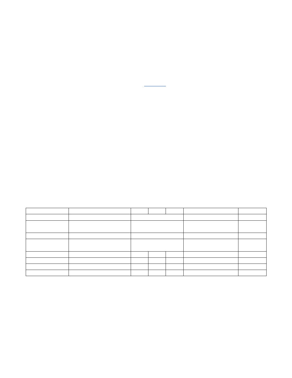
Table14-1.HardwareMultiplierOperations
MCW:MSUB:MMAC
OPERATION
MC2
MC1
MC0
MC1R:MC0R
OFSTATUS
000
Multiply
MA*MB
MA*MB
No
001
Multiply-Accumulate
MC+(MA*MB)
32lsbits of
(MC+2*(MA*MB))
Yes
010
Multiply-Negate (SUS = 0 only)
-(MA*MB)
-(MA*MB)
No
011
Multiply-Subtract
MC-(MA*MB)
32lsbits of
(MC-2*(MA*MB))
Yes
100
Multiply
MC2
MC1
MC0
MA*MB
No
101
Multiply-Accumulate
MC2
MC1
MC0
32lsbits of (MC+(MA*MB))
No
110
Multiply-Negate (SUS = 0 only)
MC2
MC1
MC0
-(MA*MB)
No
111
Multiply-Subtract
MC2
MC1
MC0
32lsbits of (MC-(MA*MB))
No