3 capture mode, 12 .1 .3 capture mode -5, Figure 12-3 . capture mode block diagram -5 – Maxim Integrated MAX31782 User Manual
Page 107: 3capturemode
MaximIntegrated 12-5
MAX31782 User’s Guide
Revision 0; 8/11
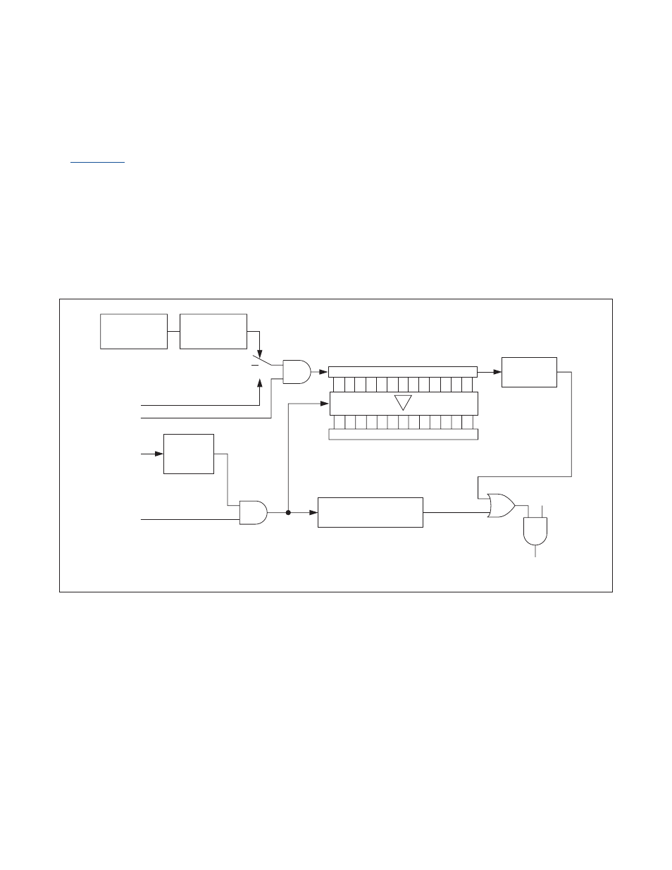
12.1.3CaptureMode
The Timer B 16-bit capture mode is configured by setting the CP/RLB bit to 1 . A block diagram of this mode is shown
in
. In capture mode, the Timer B can be clocked either by a prescaled version of the system clock or fall-
ing edges of the TBA pin . When the timer is enabled in capture mode, it begins counting up from the value contained
in the TB0V register until reaching an overflow state . An overflow state is when the TB0V register changes from FFFFh
to 0000h . When this happens, the timer overflow flag (TFB), is set, which can generate an interrupt if enabled . After an
overflow the timer continues counting upward . This counting is repeated without processor intervention until the timer
is disabled (TRB = 0) .
The current value in TB0V is captured and copied into the capture/reload register (TB0R) when a falling edge occurs on
the TBB pin and the external enable bit (EXENB) of the control register is set to 1 . The EXFB flag is set when a capture
occurs, which can generate an interrupt if enabled . If the EXENB bit is cleared to 0, transitions on the TBB pin do not
cause a capture event .
Figure 12-3. Capture Mode Block Diagram
SYSTEM
CLOCK
CLOCK PRESCALER
TBPS[2:0]
FALLING
EDGE
EXFB = 1
CLK 15
0
TB0V
TB0R
TFB = 1
15
0
CAPTURE
TBA PIN
TRB
TBB PIN
EXENB
0
1
C/TB
ETB
TIMER B
INTERRUPT