1 hardware multiplier organization, 14 .1 hardware multiplier organization -2, Figure 14-1 . multiplier organization -2 – Maxim Integrated MAX31782 User Manual
Page 117: 1hardwaremultiplierorganization
MaximIntegrated 14-2
MAX31782 User’s Guide
Revision 0; 8/11
SECTION 14: Hardware Multiplier
The hardware multiplier module can be used by the MAX31782 to support high-speed multiplications . The hardware
multiplier module is equipped with two 16-bit operand registers, a 32-bit read-only result register, and an accumulator of
48-bit width . The multiplier can complete a 16-bit x 16-bit multiply-and-accumulate/subtract operation in a single cycle .
The hardware multiplier module supports the following operations without interfering with the normal core functions:
• Signed or Unsigned Multiply (16-bit x 16-bit)
• Signed or Unsigned Multiply-Accumulate (16-bit x 16-bit)
• Signed or Unsigned Multiply-Subtract (16-bit x 16-bit)
• Signed Multiply and Negate (16-bit x 16-bit)
14.1HardwareMultiplierOrganization
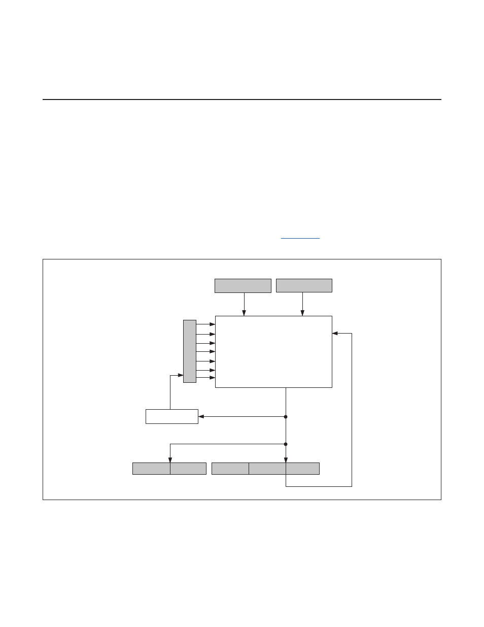
The hardware multiplier consists of two 16-bit, parallel-load operand registers (MA, MB), a read-only result register
formed by two parallel 16-bit registers (MC1R and MC0R), an accumulator, which is formed by three 16-bit parallel
registers (MC2, MC1, and MC0), and a status/control register (MCNT) .
shows a block diagram of the hard-
ware multiplier .
Figure 14-1. Multiplier Organization
MB
MA
MC0
MC1
MC2
MULTIPLIER
0
0
15
15
0
15
0
15
OVERFLOW
SUS
MMAC
MSUB
OPCS
SQU
CLD
MCW
15
0
15
15
0
0
MC1R
MC0R
MCNT