Maxim Integrated High-Speed Microcontroller Users Guide: DS80C390 Supplement User Manual
Page 99
High-Speed Microcontroller User’s Guide: DS80C390 Supplement
99 of 158
Having selected the memory configuration, the following SFR settings affect the example memory map:
SA EQU 1 ; Use 1KB stack in on-chip XDATA space
IDM EQU 2 ; 2 = 4KB on-chip SRAM location X:0x400000 – X:400FFF
CMA EQU 1 ; 1 = CAN0 X:0x401000 – X:0x4010FF
; CAN1 X:0x401100 – X:0x4011FF
P4CNT5_3 EQU 110B ; 110B = 512kB (A18-A0 enabled)
P4CNT2_0 EQU 101B ; 101B = enable CE0, CE1
P5CNT2_0 EQU 110B ; 110B = enable PCE0, PCE1, PCE2
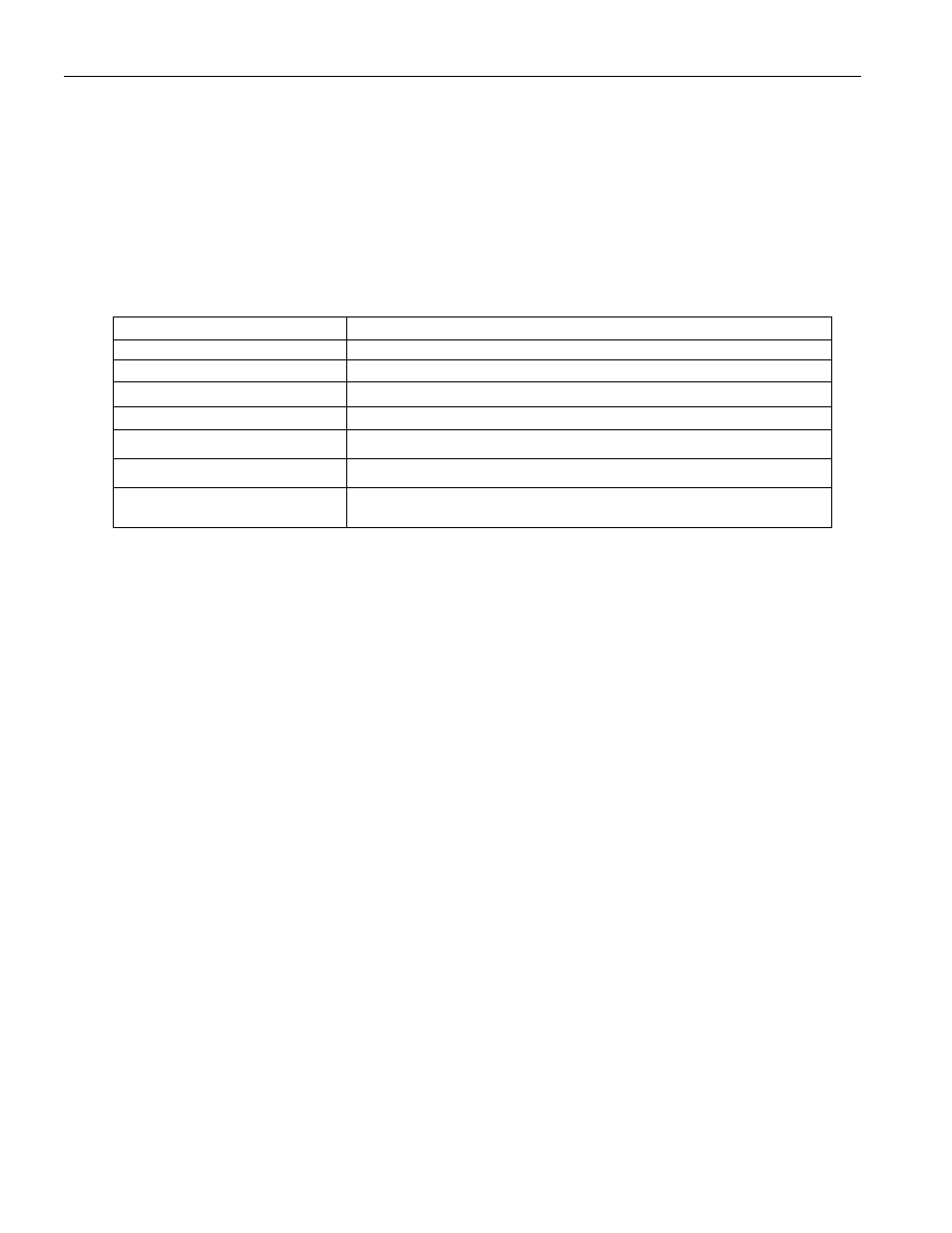
When complete, chip-enable signals should be active when indicated below:
CHIP-ENABLE ACCESS
ACTIVITY
CE0 accesses with PSEN\
Program fetches from low 512kB and MOVC read to 07FFFFH
CE1 access with PSEN\
MOVC read to 080000H
PCE0 access with RD\
MOVX access to 07FFFFH
PCE1 access with RD\
MOVX access to 080000H
PCE1 access with RD\
MOVX access to 0FFFFFH
PCE2 access with RD\
MOVX access to 100000H
—
MOVX operation to 400000H accesses internal XRAM and can
be verified by viewing the contents of ACC inside of the simulator
- DS80C390 (58 pages)
- DS5001FP (26 pages)
- MAX1416 (14 pages)
- MAX5865 (18 pages)
- DS33Z41 (167 pages)
- MAX1202 (7 pages)
- USBTO232 (31 pages)
- HFAN-09.5.0: Pattern Creator/Converter Software (8 pages)
- MAX-IDE MAXQ Microcontrollers (11 pages)
- MAX6876 Power-Supply Tracker/Sequencer (6 pages)
- MAX6877 Power-Supply Tracker/Sequencer (3 pages)
- 78Q8430 ARM9(920T) Linux Driver Diagnostic Guide (19 pages)
- 78Q8430 Software Driver (54 pages)
- 78Q8430 ST 5100/OS-20 with NexGen TCP/IP Stack (28 pages)
- 6612_OMU_S2_URT_V1_13 (56 pages)
- 6612_OMU_S2+2_URT_V1_14 (58 pages)
- 71M6511 Power Meter IC Family Software (137 pages)
- 71M65xx ADM51 ICE Safety Notice (2 pages)
- 71M6511 2-Layer Demo Board (2 pages)
- 71M6511 4-Layer Demo Board (2 pages)
- 78Q8430 Linux Driver ARM Platform (22 pages)
- 71M6513 Demo Board (2 pages)
- 71M6521DE Energy Meter IC Family Software (138 pages)
- 71M6521 Demo Board (2 pages)
- 71M6531 Demo Board (2 pages)
- 71M6531 Energy Meter IC Family Software (116 pages)
- 71M6533 Demo Board (2 pages)
- 71M6534H Demo Board (2 pages)
- 71M6515H Demo Board (2 pages)
- 73S1209F Evaluation Board (2 pages)
- 73S12xxF (38 pages)
- 73S12xxF Software (93 pages)
- 73S1210F Evaluation Board Lite (2 pages)
- 73S1210F Evaluation Board (2 pages)
- 73S1210F Multi-SAM Evaluation Board Lite (2 pages)
- 73S12xxF USB-CCID Linux DFU Host Application (8 pages)
- 73S1215F Device Firmware Upgrade Host Driver/Application (10 pages)
- 73S12xxF USB-CCID Host GUI (22 pages)
- 73S1215F Windows XP 32 USB CCID and DFU Drivers (15 pages)
- 73S1215F CCID USB Linux Driver (16 pages)
- 73S1215F Evaluation Board (2 pages)
- 73S1215F Evaluation Board Lite (2 pages)
- 73S1217F Evaluation Board (2 pages)
- 73S1217F Evaluation Board Lite (2 pages)
- MAXQ Family (216 pages)