Remote frame (standard and extended format), Error frame – Maxim Integrated High-Speed Microcontroller Users Guide: DS80C390 Supplement User Manual
Page 137
High-Speed Microcontroller User’s Guide: DS80C390 Supplement
137 of 158
Remote Frame (Standard and Extended Format)
The Remote Frame is transmitted by a CAN controller to request the transmission of the Data Frame with
the same identifier. The Remote Frame is composed of seven fields. These include the Start of Frame,
Arbitration Field, Control Field, Data Field, CRC Field, Acknowledge Field and an End of Frame.
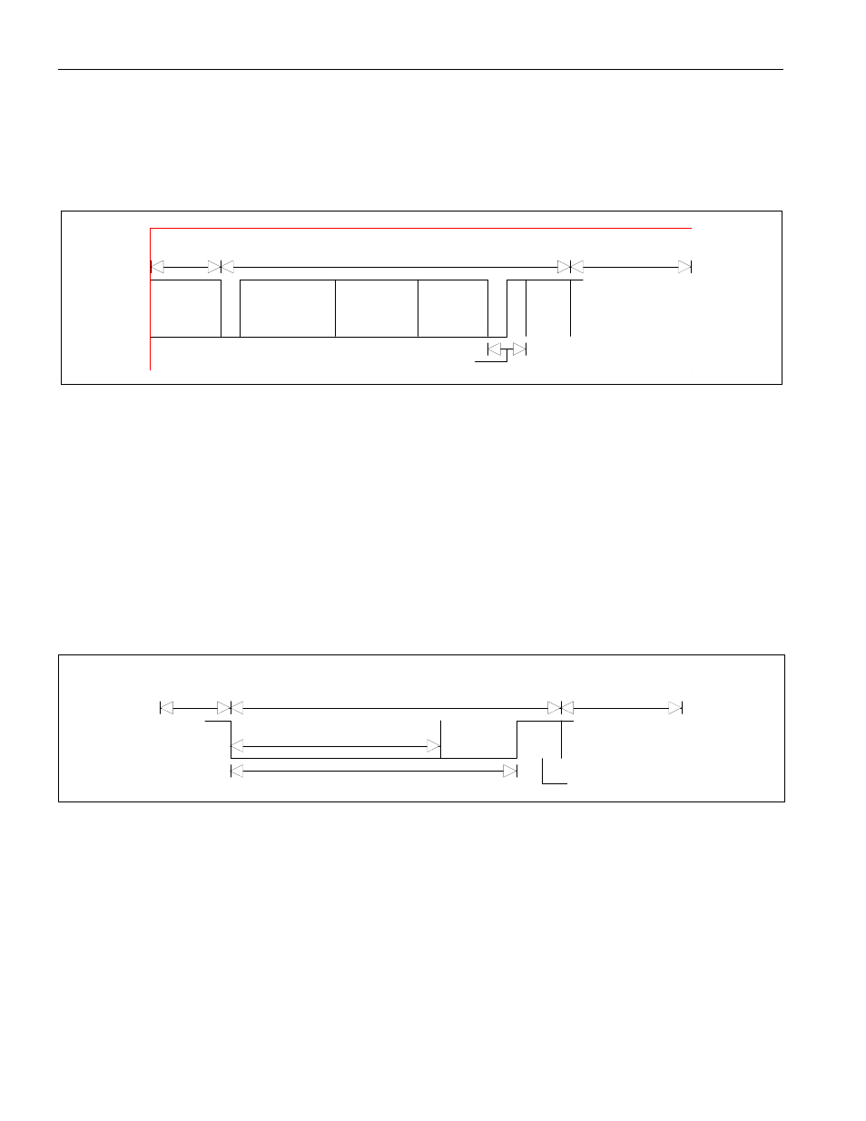
Figure 19-7. REMOTE FRAME
S
O
F
Arbitration Field
Remote Frame
ACK Field
Interframe Space
or Overload Frame
End of
Frame
Control Field CRC Field
Interframe
Space
The Remote Frame is used when a CAN processor wishes to request data from another node. Sending a
Remote Frame initiates a transmission of data from a source node with the same identifier (masked
groups included). The primary bit pattern difference between a Data Frame and a Remote Frame is the
RTR bit, which in the Remote Frame is sent as a recessive bit, and in the Data Frame is sent as a
dominant bit. The Remote Frame also does not contain a data field, independent of the programmed
values in the DTBYC3 - DTBYC0 bits in the respective CAN Message Format Register.
Error Frame
The Error Frame is transmitted by a CAN controller when the CAN processor detects a bus error. The
Error Frame is composed of two different fields. These are 1) the superposition of the Error Flags from
different nodes and 2) the Error Delimiter.
Figure 19-8. ERROR FRAME
Error Frame
Superposition of Error Flags from other nodes
Interframe Space
or Overload Frame
Data Frame
Error Flag
Error Delimiter
The Error Frame is composed of six dominant bits, which violate the CAN specification bit stuffing rule.
If either of the CAN processors detect an error condition, that CAN processor will transmit an Error
Frame. When this happens all nodes on the bus will detect the bit stuff error condition and will transmit
their own Error Frame. The superpositioning of all of these Error Frames will lead to a total Error Frame
length between 6 and 12 bits, depending on the response time and number of nodes in the system. Any
messages (Data or Remote Frame) received by the CAN processors (successful or not) which are
followed by an Error Frame will be discarded. After the transmission of an Error Flag each CAN
processor will send an error delimiter (eight recessive bits) and will monitor the bus until it detects the
change from the dominant to recessive bit level. The CAN modules will issue an Error Frame each time
an Error Frame is detected. Following a series of Error Frames the CAN modules will enter into an Error
Passive Mode. In the Error Passive Mode the CAN processors will transmit six recessive bits, and wait