Addendum to section 5: cpu timing, System clock selection – Maxim Integrated High-Speed Microcontroller Users Guide: DS80C390 Supplement User Manual
Page 91
High-Speed Microcontroller User’s Guide: DS80C390 Supplement
91 of 158
ADDENDUM TO SECTION 5: CPU TIMING
SYSTEM CLOCK SELECTION
The internal clocking options of the DS80C390 differs slightly from that described in the High-Speed
Microcontroller User’s Guide
. Most members of the family offer the option of 4, 256, or 1024 oscillator
clocks per machine cycle. The DS80C390 can operate at 1, 2, 4, or 1024 clocks per machine cycle. The
logical operation of the system clock divide control function is shown below. A 3:1 multiplexer,
controlled by CD1, CD0 (PMR.7-6), selects one of three sources for the internal system clock:
Crystal oscillator or external clock source
(Crystal oscillator or external clock source) divided by 256
(Crystal oscillator or external clock source) frequency multiplied by 2 or 4 times
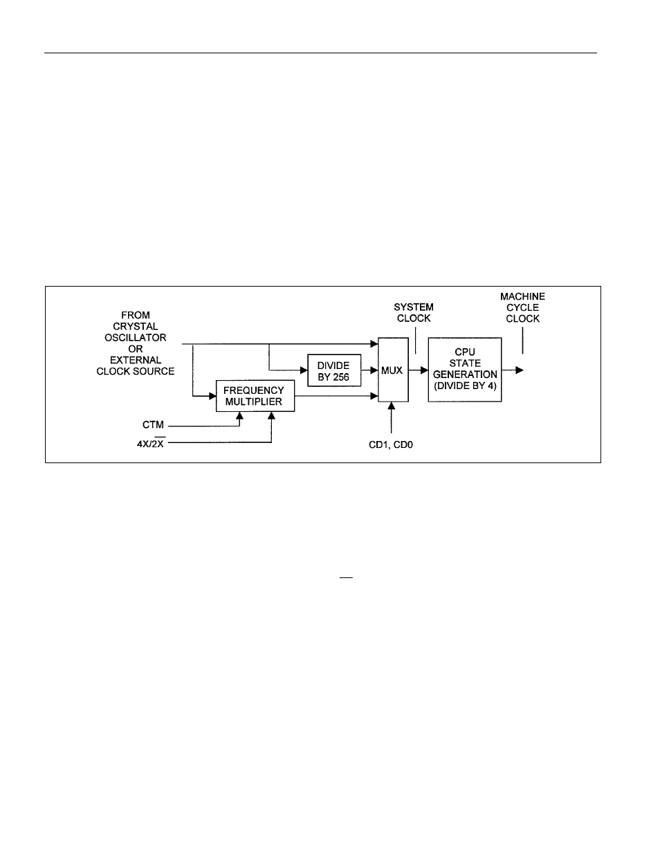
Figure 5-1. SYSTEM CLOCK CONTROL DIAGRAM
The system clock control circuitry generates two clock signals that are used by the microcontroller. The
internal system clock
provides the timebase for timers and internal peripherals. The system clock is run
through a divide-by-4 circuit to generate the machine cycle clock that provides the timebase for CPU
operations. All instructions execute in one to six machine cycles. It is important to note the distinction
between these two clock signals, as they are sometimes confused, creating errors in timing calculations.
Setting CD1, CD0 to 0 enables the frequency multiplier, either doubling or quadrupling the frequency of
the crystal oscillator or external clock source. The
2X
4X/
bit controls the multiplying factor, selecting
twice or four times the frequency when set to 0 or 1, respectively. Enabling the frequency multiplier
results in apparent instruction execution speeds of 2 or 1 clocks. Regardless of the configuration of the
frequency multiplier, the system clock of the microcontroller can never be operated faster than 40MHz.
This means that the maximum crystal oscillator or external clock source is 10MHz when using the 4X
setting, and 20MHz when using the 2X setting.
The primary advantage of the clock multiplier is that it allows the microcontroller to use slower crystals
to achieve the same performance level. This reduces EMI and cost, as slower crystals are generally more
available and thus less expensive.