Overload frame – Maxim Integrated High-Speed Microcontroller Users Guide: DS80C390 Supplement User Manual
Page 138
High-Speed Microcontroller User’s Guide: DS80C390 Supplement
138 of 158
until six equal bits of the same polarity have been detected. At this point the CAN processor will begin
the next internal receive or transmission operation.
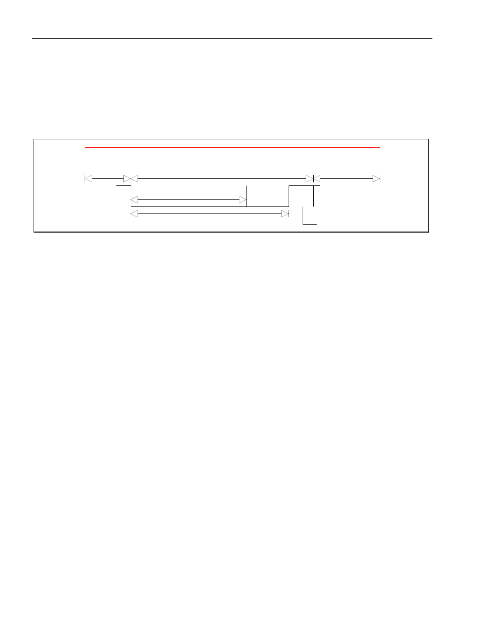
Overload Frame
The Overload Frame provides an extra delay between Data or Remote Frames. The Overload Frame is
composed of two different fields: the Overload Flag and the Overload Delimiter.
Figure 19-9. OVERLOAD FRAME
Overload Frame
Superposition of Overload Flags from other nodes
Interframe Space
or Overload Frame
End of Frame or
Error Delimiter or
Overload Delimiter
Overload Flag
Overload Delimiter
Three conditions lead to the transmission of an overload flag:
1. The internal conditions of a CAN receiver require a delay before the next Data or Remote Frame is
sent. The DS80C390 CAN controllers are designed to prevent this condition for data rates at or below
the 1 Mbit per second data rate.
2. The CAN processor detects a dominant bit at the first and second bit position of the Intermission.
3. If the CAN processor detects a dominant bit at the eighth bit of an Error Delimiter or Overload
Delimiter, it will start transmitting an Overload Frame.
The error counters will not be incremented as a result of number 3. The CAN processor will only start an
Overload Frame at the first bit of an expected Intermission if initiated by condition 1. Conditions 2 and 3
will result in the CAN processor transmitting an Overload Frame starting one bit after detecting the
dominant bit. The Overload Flag consists of six dominant bits that correspond to an Error Flag. Because
the Overload Frame is only transmitted at the first bit time of the Interframe Space, it is possible for the
CAN processor to discriminate between an Error Frame and an Overload Frame. The Overload Flag
destroys the Intermission field. When such a condition is detected, the CAN processor will detect the
Overload condition and will begin transmitting an Overload Frame. After the transmission of an Overload
Frame the CAN processors will monitor the bus for a dominant to recessive level change. The CAN
processor will then begin the transmission of six additional recessive bits, for a total of seven recessive
bits on the bus. The Overload Delimiter consists of eight recessive bits.