Irda clock output, Da c, Lock – Maxim Integrated High-Speed Microcontroller Users Guide: DS80C390 Supplement User Manual
Page 111: Utput
High-Speed Microcontroller User’s Guide: DS80C390 Supplement
111 of 158
IrDA CLOCK OUTPUT
The Infrared Data Association (IrDA) communication protocol is a popular way to connect physically
separated devices up to one meter distant. The physical layer of the protocol is very easy to implement:
configure the DS80C390’s serial port 0 by selecting crystal speed, baud rate, etc. The microcontroller is
then connected to an external IR encoder/decoder that modulates the output of the serial port and
communicates with an infrared transceiver. A good reference for the implementation of IrDA interfaces
can be found in IrDA Data Link Design Guide available from Hewlett-Packard Company,
The DS80C390 incorporates special circuitry that makes it a snap to add IR capability to your design.
Most IR encoders require the controlling microprocessor to supply a 16x clock to perform the
modulation. The DS80C390 can provide this special 16x clock to the encoder without requiring the use of
a timer. After the serial port is configured, set the IRDACK (COR.7) and CLKOE (COR.0) bits using the
Timed Access procedure. The P3.5 latch bit (P3.5) must also be set. At this point a clock signal with a
frequency of 16 times the serial port 0 baud rate will be presented on P3.5.
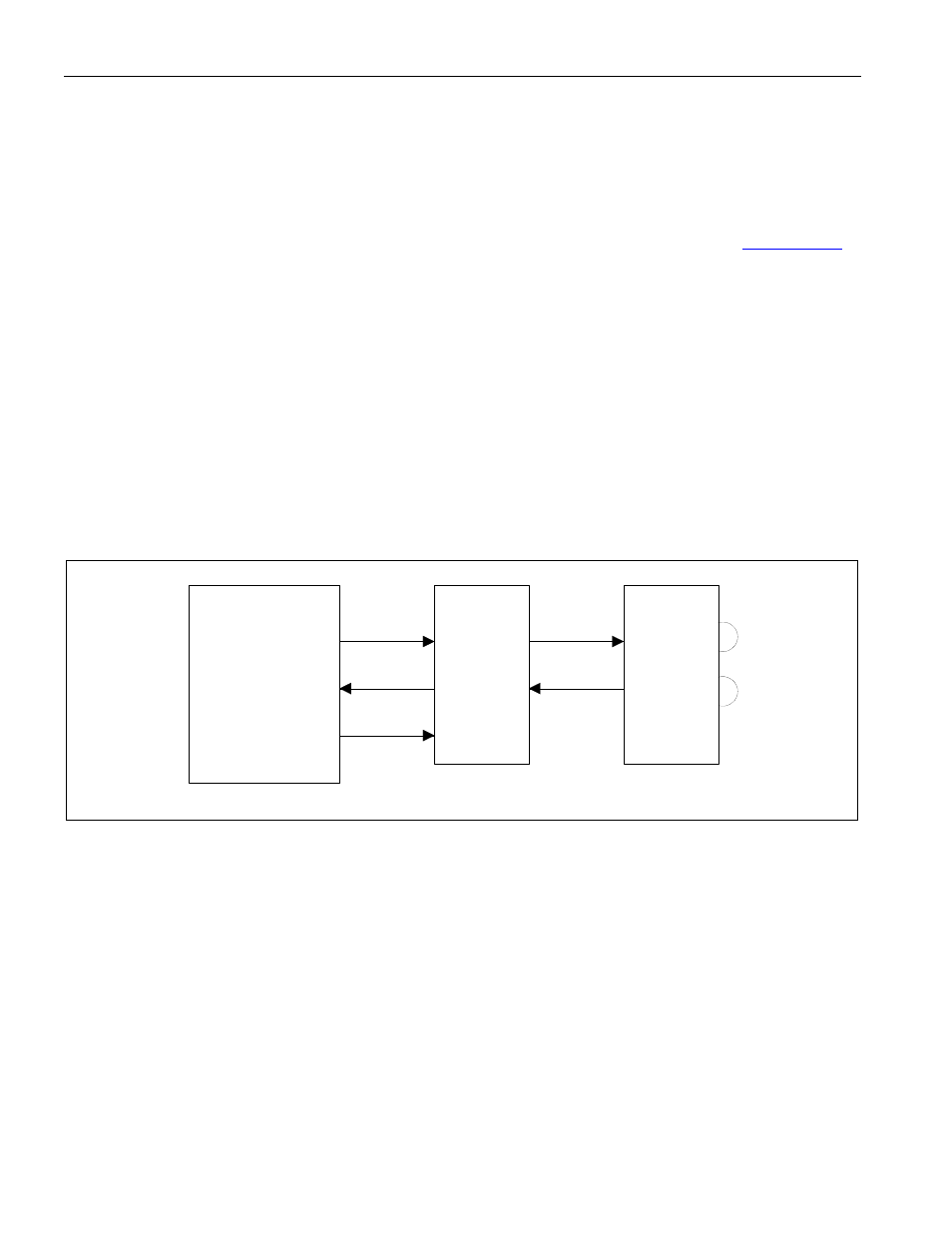
The following diagram illustrates how to add IrDA capability to a DS80C390-based system. The receive
and transmit signals of serial port 0 are connected directly to an encoder/decoder chip which in turn
interfaces to an infrared transceiver. The External Clock Output pin (P3.5) is connected to the 16XCLK
pin of the encoder/decoder to provide the modulation clock.
Figure 11-1. Sample IRDA Implementation
P3.5
P3.0
P3.1
TXD
RXD
16x Clock
Ir TXD
Ir RXD
HSDL-7000
Encoder/
Decoder
HSDL-3610
Transceiver
DS80C390