Timer 2 control (t2con), Exf2, Imer – Maxim Integrated High-Speed Microcontroller Users Guide: DS80C390 Supplement User Manual
Page 61: Ontrol, T2con)
High-Speed Microcontroller User’s Guide: DS80C390 Supplement
61 of 158
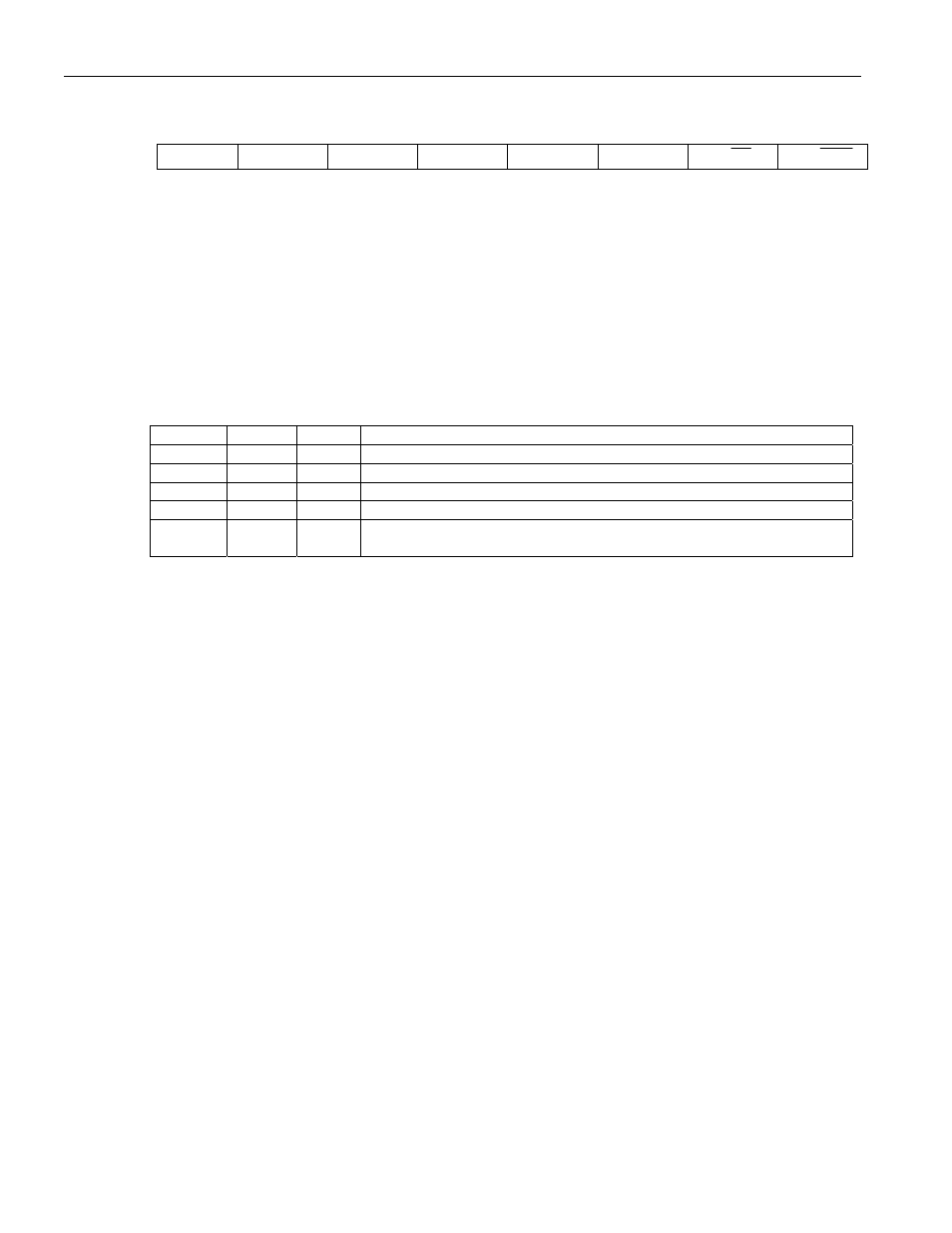
TIMER 2 CONTROL (T2CON)
7 6 5 4 3 2 1 0
SFR C8h
TF2 EXF2 RCLK TCLK
EXEN2 TR2 C/ T2 CP/ RL2
RW-0 RW-0 RW-0 RW-0 RW-0 RW-0 RW-0 RW-0
R = Unrestricted Read, W = Unrestricted Write, -n = Value after Reset
TF2
Bit 7
Timer 2 Overflow Flag. This flag will be set when Timer 2 overflows from FFFFh or the
count equal to the capture register in down count mode. It must be cleared by software. TF2
will only be set if RCLK and TCLK are both cleared to 0.
EXF2
Bit 6
Timer 2 External Flag. A negative transition on the T2EX pin (P1.1) or timer 2
underflow/overflow will cause this flag to set based on the CP/RL2 (T2CON.0), EXEN2
(T2CON.3), and DCEN (T2MOD.0) bits. If set by a negative transition, this flag must be
cleared to 0 by software. Setting this bit in software or detection of a negative transition on
the T2EX pin will force a timer interrupt if enabled.
CP/
RL2 EXEN2 DCEN
RESULT
1
0
X
Negative transitions on P1.1 will not affect this bit.
1
1
X
Negative transitions on P1.1 will set this bit.
0
0
0
Negative transitions on P1.1 will not affect this bit.
0
1
0
Negative transitions on P1.1 will set this bit.
0 X 1
Bit toggles whenever timer 2 underflows/overflows and can be used as a
17th bit of resolution. In this mode, EXF2 will not cause an interrupt.
RCLK
Bit 5
Receive Clock Flag. This bit determines the serial port 0 timebase when receiving data in
serial modes 1 or 3.
0 = Timer 1 overflow is used to determine receiver baud rate for serial port 0.
1 = Timer 2 overflow is used to determine receiver baud rate for serial port 0.
Setting this bit forces timer 2 into baud-rate generation mode. The timer operates from a
divide-by-2 of the external clock. For revisions C and later of this device, setting this bit
doubles the receiver baud rate of serial port 1. When the RCLK bit is set, the clock circuitry
assumes the serial port 1 baud-rate doubler bit (WDCON.7) is 0 for the purposes of calculating
the serial port receiver baud rate. If the system design requires the use of serial port 1 and the
setting of RCLK, then simply calculate a new reload value for serial port 1 corresponding to a
baud rate that is half the desired rate. This feature halves the doubled baud rate, allowing serial
port 1 to operate at the desired baud rate.
TCLK
Bit 4
Transmit Clock Flag. This bit determines the serial port 0 timebase when transmitting data in
serial modes 1 or 3.
0 = Timer 1 overflow is used to determine transmitter baud rate for serial port 0.
1 = Timer 2 overflow is used to determine transmitter baud rate for serial port 0.
Setting this bit forces timer 2 into baud-rate generation mode. The timer operates from a
divide-by-2 of the external clock. For revisions C and later of this device, setting this bit
doubles the transmitter baud rate of serial port 1. When the TCLK bit is set, the clock circuitry
assumes the serial port 1 baud-rate doubler bit (WDCON.7) is 0 for the purposes of calculating
the serial port receiver baud rate. If the system design requires the use of serial port 1 and the
setting of TCLK, then simply calculate a new reload value for serial port 1 corresponding to a
baud rate that is half the desired rate. This feature halves the doubled baud rate, allowing serial
port 1 to operate at the desired baud rate.
EXEN2
Bit 3
Timer 2 External Enable. This bit enables the capture/ reload function on the T2EX pin if
Timer 2 is not generating baud rates for the serial port.
0 = Timer 2 will ignore all external events at T2EX.
1 = Timer 2 will capture or reload a value if a negative transition is detected on the T2EX pin.