Addendum to section 11: programmable timers, Timer/counter 0 and 1 modes 0 and 1 – Maxim Integrated High-Speed Microcontroller Users Guide: DS80C390 Supplement User Manual
Page 106
High-Speed Microcontroller User’s Guide: DS80C390 Supplement
106 of 158
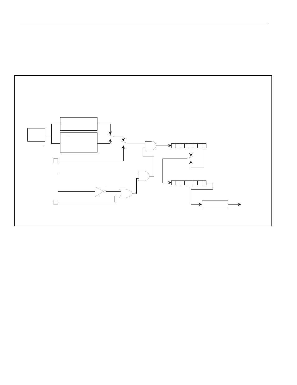
ADDENDUM TO SECTION 11: PROGRAMMABLE TIMERS
The timers of the DS80C390 are very similar to the those of described in the High-Speed Microcontroller
User’s Guide.
The primary changes concern the removal of the PMM2 option and the inclusion of the
frequency multiplier settings. The following figures replace the corresponding figures in Section 11 of the
High-Speed Microcontroller User’s Guide
. The affect on the timers is summarized in tabular form in
Section 5, Table 5-2, Effect of Clock Modes on Timer Operation.
OSC
0
1
T0M = CKCON.3
(T1M = CKCON.4)
T0 = P3.4
(T1 = P3.5)
C/T = TMOD.2
(C/T = TMOD.6)
0
1
0
7
GATE = TMOD.3
(GATE = TMOD.7)
/INT0 = P3.2
(/INT1 = P3.3)
TR0 = TCON.4
(TR1 = TCON.6)
7
0
00
01
M1,M0 = TMOD.1, TMOD.0
(M1,M0 = TMOD.5, TMOD.4)
INTERRUPT
TL0
(TL1)
TH0
(TH1)
TF0 = TCON.5
(TF1 = TCON.7)
TIMER 1 FUNCTIONS
SHOWN IN PARENTHESIS ()
TIMER/COUNTER 0 AND 1
MODES 0 AND 1
MODE 0
MODE 1
4
/CLK
4X/
2X CD1:0 CLK OUT
1 00 /1
0 00 /2
x 10 /4
x 11 /1024
CD1:0 CLK OUT
11 /3,072
anything else /12