Maxim Integrated High-Speed Microcontroller Users Guide: DS80C390 Supplement User Manual
Page 154
High-Speed Microcontroller User’s Guide: DS80C390 Supplement
154 of 158
The timing of the various time segments is determined by the following formulae. Most users will never
need to perform these calculations, as other devices already attached to the network will dictate the bus
timing parameters.
OSC
QU
f
CCD
BRPV
t
⋅
=
QU
SEG
_
SYNC
t
t
⋅
= 1
QU
TSEG
t
)
LEN
_
TS
(
t
⋅
=
1
1
QU
TSEG
t
)
LEN
_
TS
(
t
⋅
=
2
2
QU
SJW
t
)
SJW
(
t
⋅
=
QU
bit
per
QU
t
rate
baud
t
⋅
=
1
(only integer values are permitted),
where BPRV is the CAN baud rate prescaler value found in the description of the C0BT0/C1BT0
registers, F
OSC
is the crystal or external oscillator frequency of the microprocessor, and TS1_LEN and
TS2_LEN are listed in the description of the TSEG26-24 and TSEG13-10 bits in the CAN Bus Timing
Register 1. SJW is listed in the description of the SJW1-0 bits in the CAN Bus Timing Register 0. The
CCD is the CAN clock divide value, calculated from the following table.
CD1 CD0
4X/ 2X
CCD
0 0 1
0.5
0 0 0
1
1 0 x
2
1 1 x
512
The following restrictions apply to the above equations:
t
TSEG1
≥ t
TSEG2
t
TSEG2
≥ t
SJW
t
SJW
< t
TSEG1
2
≤ TS1_LEN ≤ 16
2
≤ TS2_LEN ≤ 8
(TS1_LEN + TS2_LEN +1)
≤ 25
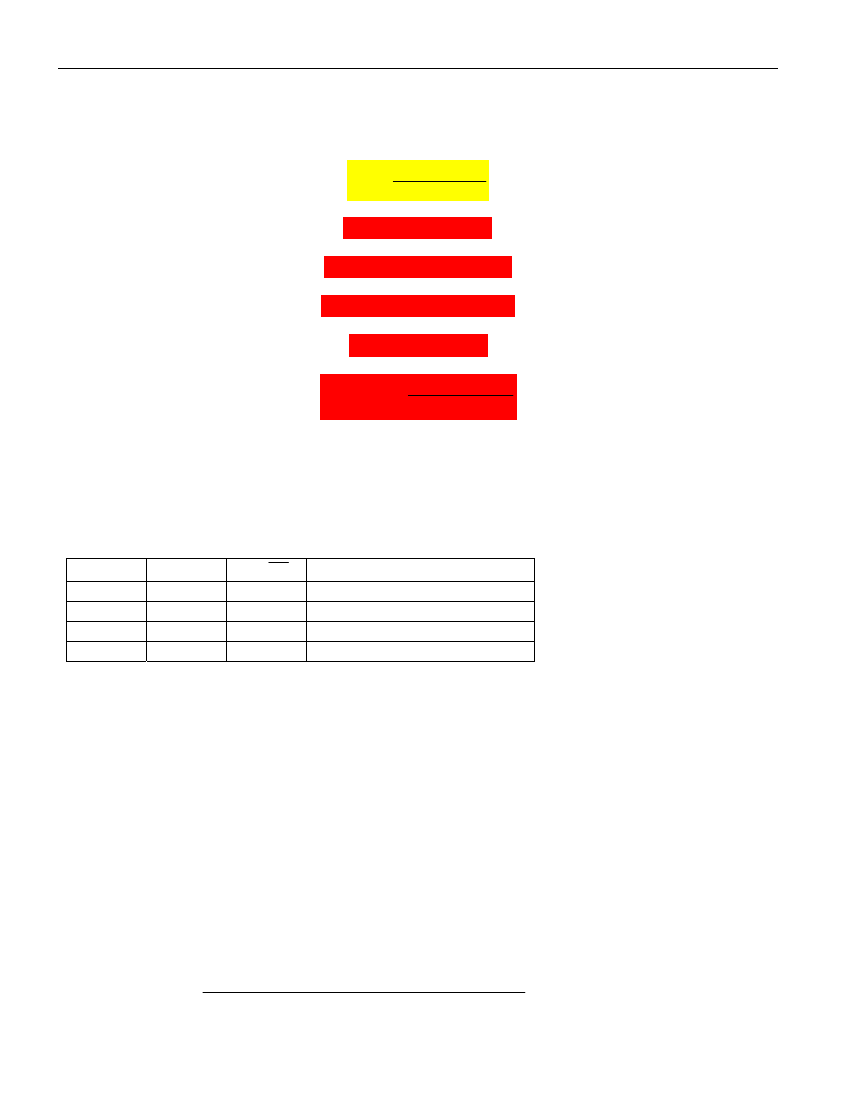
The nominal bit time applies when a synchronization edge falls within the t
SYNC_SEG
period. The
maximum bit time occurs when the synchronization edge falls outside of the t
SYNC_SEG
period, and the
synchronization jump width time is added to perform the resynchronization.
nominal bit time = t
SYNC_SEG
+ t
TSEG1
+ t
TSEG2
=
OSC
F
)]
LEN
_
2
TS
(
)
LEN
_
1
TS
(
1
)[
CCD
)(
BRPV
(
+
+