Figure 19-11 – Maxim Integrated High-Speed Microcontroller Users Guide: DS80C390 Supplement User Manual
Page 153
High-Speed Microcontroller User’s Guide: DS80C390 Supplement
153 of 158
Figure 19-11.
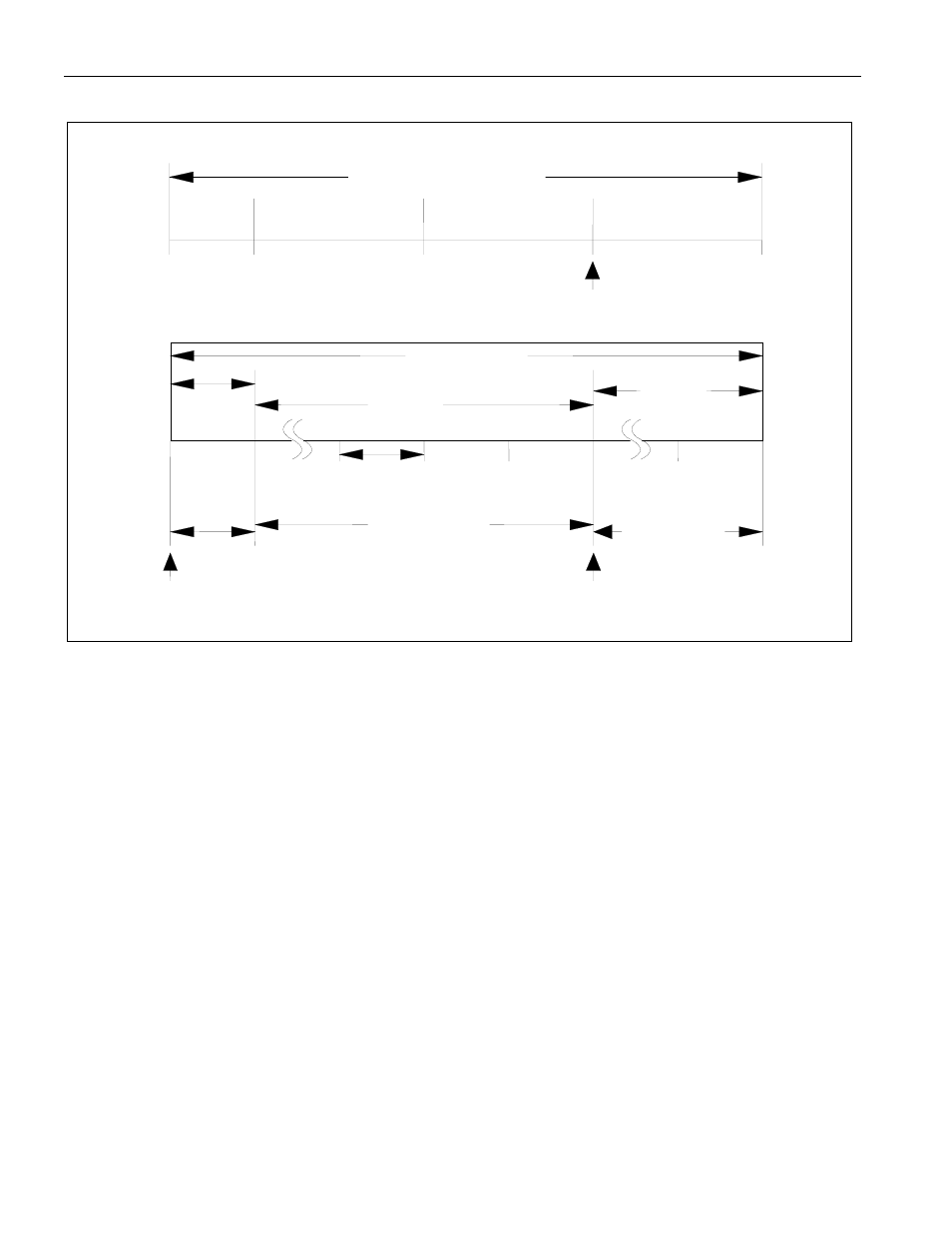
BIT TIMING
The CAN 0/1 Bus Timing Register Zero (C0BT0/C1BT0) contains the control bits for the PHASE_SEG1
and PHASE_SEG2 time segments as well as the Baud Rate Prescaler (BPR5-0) bits. CAN 0/1 Bus
Timing Register One (C0BT1/C1BT1) controls the sampling rate, the Time Segment Two bits that
control the number of clock cycles assigned to the Phase Segment 2 portion, and the Time segment One
bits that determine the number of clock cycles assigned to the Phase Segment 1 portion. The value of both
of the Bus Timing registers are automatically loaded into the CAN module following each software
change of the SWINT bit from a 1 to a 0 by the microcontroller. The bit timing parameters must be
configured before starting operation of the CAN module. These registers can only be modified during a
software initialization (SWINT = 1), when the CAN module is not in a bus-off mode, and after the
removal of a system reset or a CAN reset. To avoid unpredictable behavior of the CAN module the Bus
Timing Registers should never be written with all zeros. To prevent this the SWINT is forced to 0 when
TSEG1 = TSEG2 = 00h.
t
TSEG1
1 Bit Time
1 t
QU
Time Quanta
TRANSMIT
SAMPLE
POINT
SYNC_SEG
PROP_SEG
PHASE_SEG1
PHASE_SEG2
Nominal Bit Time
t
TSEG2
t
SYNC-SEG
SAMPLE
POINT
1 t
QU
Time Quanta
2 t
QU
– 16 t
QU
2 t
QU
– 8 t
QU