In-system disable mode – Maxim Integrated High-Speed Microcontroller Users Guide: DS80C390 Supplement User Manual
Page 103
High-Speed Microcontroller User’s Guide: DS80C390 Supplement
103 of 158
contents are not altered. Interrupts and Timers are disabled. The state of the Watchdog Timer is
dependent on the specific device in use. Note that the Watchdog time out defaults to its shortest interval
on any reset. I/O Ports are taken to a weak high state (FFh). This leaves each port pin configured with the
data latch set to a 1. Ports do not go to the 1 state instantly when a reset is applied, but will be taken high
within two machine cycles of asserting a reset. When the reset stimulus is removed, program execution
begins at address 0000h.
IN-SYSTEM DISABLE MODE
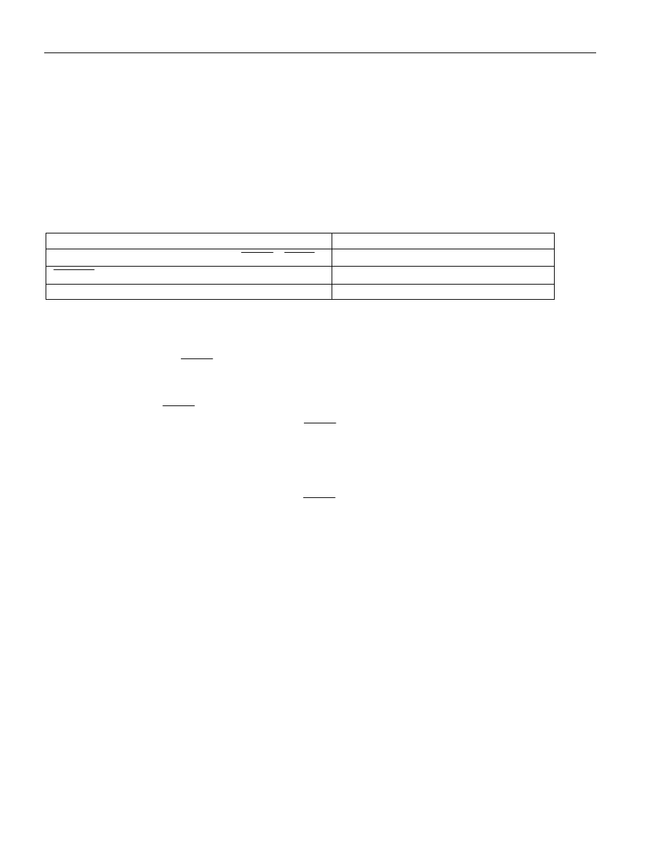
The In-System Disable (ISD) feature allows the device to be tri-stated for in-circuit emulation or board
testing. During ISD mode, the device pins will take on the following states:
DEVICE PIN
STATE DURING ISD
Port 0, 1, 2, 3, 4, 5, RST, EA, ALE, PSEN , MUX
True Tristate
RSTOL
Driven per V
OH3
specification
XTAL1, XTAL2
Oscillator remains active
The following procedure is used to enter ISD mode:
1. Assert reset by pulling RST high,
2. Pull ALE low and pull PSEN high,
3. Verify that P2.7, P2.6, P2.5 are not being driven low,
4. Release RST,
5. Hold ALE low and PSEN high for at least 2 machine cycles,
6. Device is now in ISD mode. Release ALE and PSEN if desired.
Note that pins P2.7, P2.6, P2.5 should not be driven low when RST is released. This will place the device
into a reserved test mode. Because these pins have a weak pullup during reset, they can be left floating.
The test mode is only sampled on the falling edge of RST, and once RST is released their state will not
effect device operation. In a similar manner, the PSEN and RST pins can be released once ISD mode is
invoked, and their state will not affect device operation. The RST pin will also be in a tristate mode, but
asserting it in ISD mode will return the device to normal operation.