Chapter 8: configuration information, Chapter 8, Configuration information – AERCO ProtoNode Gateway Rev 3 (with external LEDs) User Manual
Page 44: Aerco protonode gateway
AERCO ProtoNode Gateway
User Manual
Page 44 of 126
AERCO International, Inc. • 100 Oritani Dr. • Blauvelt, NY 10913
OMM-0080_0H
11/06/2014
Ph.: 800-526-0288
GF-129
CHAPTER 8:
Configuration Information
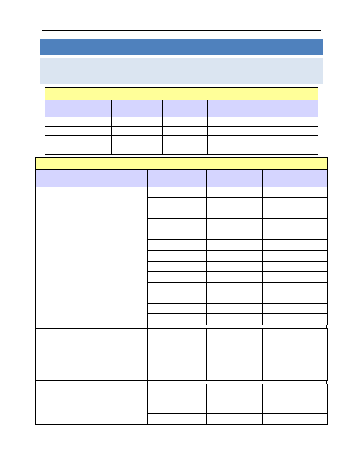
8.1 Default ProtoNode Modbus RTU COM Settings for AERCO
Controllers
Table 8-1: Default Serial Port Settings
Serial Port Setting
ACS, BMS II,
BMS
ECS/SP
BCM
(Modulex)
C-More
Baud Rate
9600
9600
9600
9600
Data Bits
8
8
8
8
Stop Bits
1
1
1
1
Parity
None
None
None
None
Table 8-2: Default Address Settings
Configuration
Controllers
Name
Modbus Default
Address
4 C-More Controllers
up to
12 C-More Controllers
&
1 ACS/BMS II/BMS
C-more 1
Blr Addr 1
1
C-more 2
Blr Addr 2
2
C-more 3
Blr Addr 3
3
C-more 4
Blr Addr 4
4
C-more 5
Blr Addr 5
5
C-more 6
Blr Addr 6
6
C-more 7
Blr Addr 7
7
C-more 8
Blr Addr 8
8
C-more 9
Blr Addr 9
9
C-more 10
Blr Addr 10
10
C-more 11
Blr Addr 11
11
C-more 12
Blr Addr 12
12
ACS /BMS II
BMS Addr 128
128
4 Modulex Controllers
&
1 ACS/BMS II/BMS
Modulex 1
Mlx Addr 1
1
Modulex 2
Mlx Addr 2
2
Modulex 3
Mlx Addr 3
3
Modulex 4
Mlx Addr 4
4
ACS /BMS II
BMA Addr 128
128
4 ECS/SP
ECS 1
E Value Addr 29
29
ECS 2
E Value Addr 30
30
ECS 3
E Value Addr 31
31
ECS 4
E Value Addr 32
32
For Profiles defined in Appendix C, the ECS/SP Modbus default point addresses are defined
below.