3 power-up of protonode rer or protonode ler, Power-up of protonode rer or protonode ler, Aerco protonode gateway – AERCO ProtoNode Gateway Rev 3 (with external LEDs) User Manual
Page 24
AERCO ProtoNode Gateway
User Manual
Page 24 of 126
AERCO International, Inc. • 100 Oritani Dr. • Blauvelt, NY 10913
OMM-0080_0H
11/06/2014
Ph.: 800-526-0288
GF-129
4.2 Wiring the ProtoNode LER Field Port to a LonWorks Network
Connect the ProtoNode to the field network with the LonWorks terminal using a twisted pair
non-shielded cable. LonWorks has no polarity.
Figure 4-3: ProtoNode LER LonWorks Field Port Terminal
4.3 Power-Up of ProtoNode RER or ProtoNode LER
Apply power to ProtoNode. Ensure that the power supply used complies with the specifications
provided in Appendix A.1. Ensure that the cable is grounded using the “Frame-GND” terminal.
ProtoNode accepts either 9-30VDC or 12-24 VAC.
Table 4-2: Power Requirement for ProtoNode at 9V through 30 VDC or 12-24 VAC
ProtoNode Family
Current Draw Type
12VDC/VAC 24VDC/VAC
30VDC
ProtoNode RER (Typical)
170mA
100mA
80mA
ProtoNode RER (Maximum)
240mA
140mA
100mA
ProtoNode LER (Typical)
210mA
100mA
90mA
ProtoNode LER (Maximum)
250mA
130mA
100mA
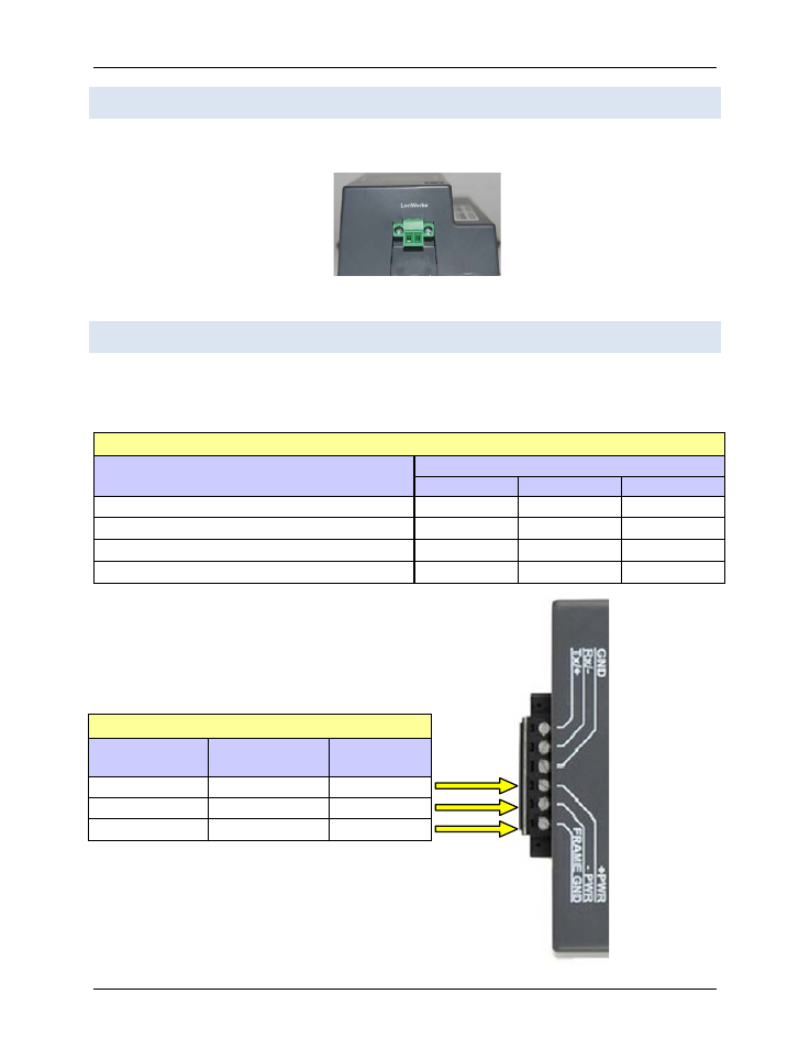
Figure 4-4: Power Connections
Table 4-3: ProtoNode Power Connections
ProtoNode
Pin #
Power to
ProtoNode
Pin
Assignment
Pin 4
Power In (+)
V +
Pin 5
Power In (-)
V -
Pin 6
Frame Ground
FRAME GND