1 accessing the pmc board in the c-more controller, Aerco protonode gateway – AERCO ProtoNode Gateway Rev 3 (with external LEDs) User Manual
Page 21
AERCO ProtoNode Gateway
User Manual
OMM-0080_0H
AERCO International, Inc. • 100 Oritani Dr. • Blauvelt, NY 10913
Page 21 of 126
GF-129
Ph.: 800-526-0288
11/06/2014
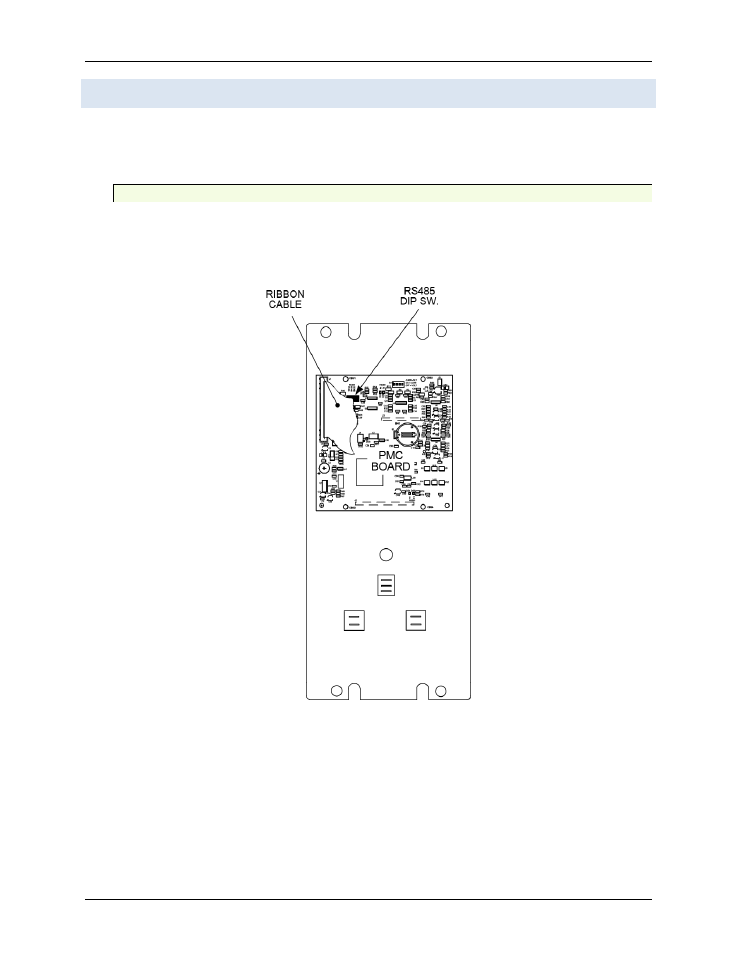
3.8 AERCO C-More Controller PMC Board DIP Switch Settings
The RS485 DIP switches (S1 bank) on the C-More controller PMC PCB must be configured
properly for use with a ProtoNode. The PMC PCB is accessed by removing the four Phillips
screws at the corners of the C-More Controller front panel. The PCB is mounted on the inside of
the front cover as shown in Figure 3-11.
3.8.1.1 Accessing the PMC Board in the C-More Controller
WARNING!
Shut off electrical power upstream of the boiler before
opening the C-More controller to avoid the danger of
electrical shock.
FIGURE 3-11: Location of RS-485 DIP Switch on C-More PMC PCB
CAUTION
The C-More Boiler Controller Printed Circuit Boards contain
electronic components that are sensitive to electrostatic discharge
(ESD). Prior to performing the following steps, put on an anti-
static wrist strap and connect the clip lead to earth ground.
Failure to observe this precaution may result in permanent
damage to on-board ESD-sensitive components.