2 biasing the modbus rs-485 network, Biasing the modbus rs-485 network, Aerco protonode gateway – AERCO ProtoNode Gateway Rev 3 (with external LEDs) User Manual
Page 17
AERCO ProtoNode Gateway
User Manual
OMM-0080_0H
AERCO International, Inc. • 100 Oritani Dr. • Blauvelt, NY 10913
Page 17 of 126
GF-129
Ph.: 800-526-0288
11/06/2014
3.3 Wiring Connections to ProtoNode RER and ProtoNode LER
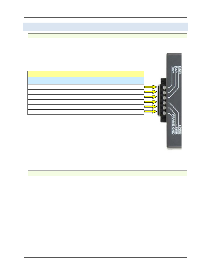
3.3.1 ProtoNode 6-Pin Phoenix Connector – Pin Outs to Modbus RTU Products
The 6 pin Phoenix connector is the same for ProtoNode RER and LER. Pins 1 through 3
are for Modbus RS-485 to the devices and pins 4 through 6 are for power.
Figure 3-3: Power and RS-485 Connections for RER and LER
3.3.2 Biasing the Modbus RS-485 Network
NOTE
Turn on biasing if the BAS cannot see the devices connected to
the ProtoNode AND you have checked all the settings (Modbus
COM settings, wiring, and DIP switches).
• An RS-485 network with more than one device may need biasing to ensure proper
communication. The biasing needs to be done on one device.
• The ProtoNode has a 510 Ohm resistor jumper that is used to set the biasing. The
ProtoNode’s default position for the Biasing jumper is OFF from the factory.
• The OFF position is when the 2 RED biasing jumpers straddle the 4 pins closest to the
outside of the board of the ProtoNode. See Figure 3-4.
TABLE 2-6: 6-Pin Phoenix Connector Outputs to Modbus RTU
Pin#
Device Pins
Pin assignment
Pin 1
Pin RS-485 +
RS-485 +
Pin 2
Pin RS-485 -
RS-485 -
Pin 3
Pin GND
-
Pin 4
Power In (+)
V +
Pin 5
Power In (-)
V -
Pin 6
Frame Ground
FRAME GND