Rockwell Automation Liqui-Flo AC GP Vector Drive Version 6.4 User Manual
Page 218
G-8
LiquiFlo AC Drive, Software Reference Version 6.4
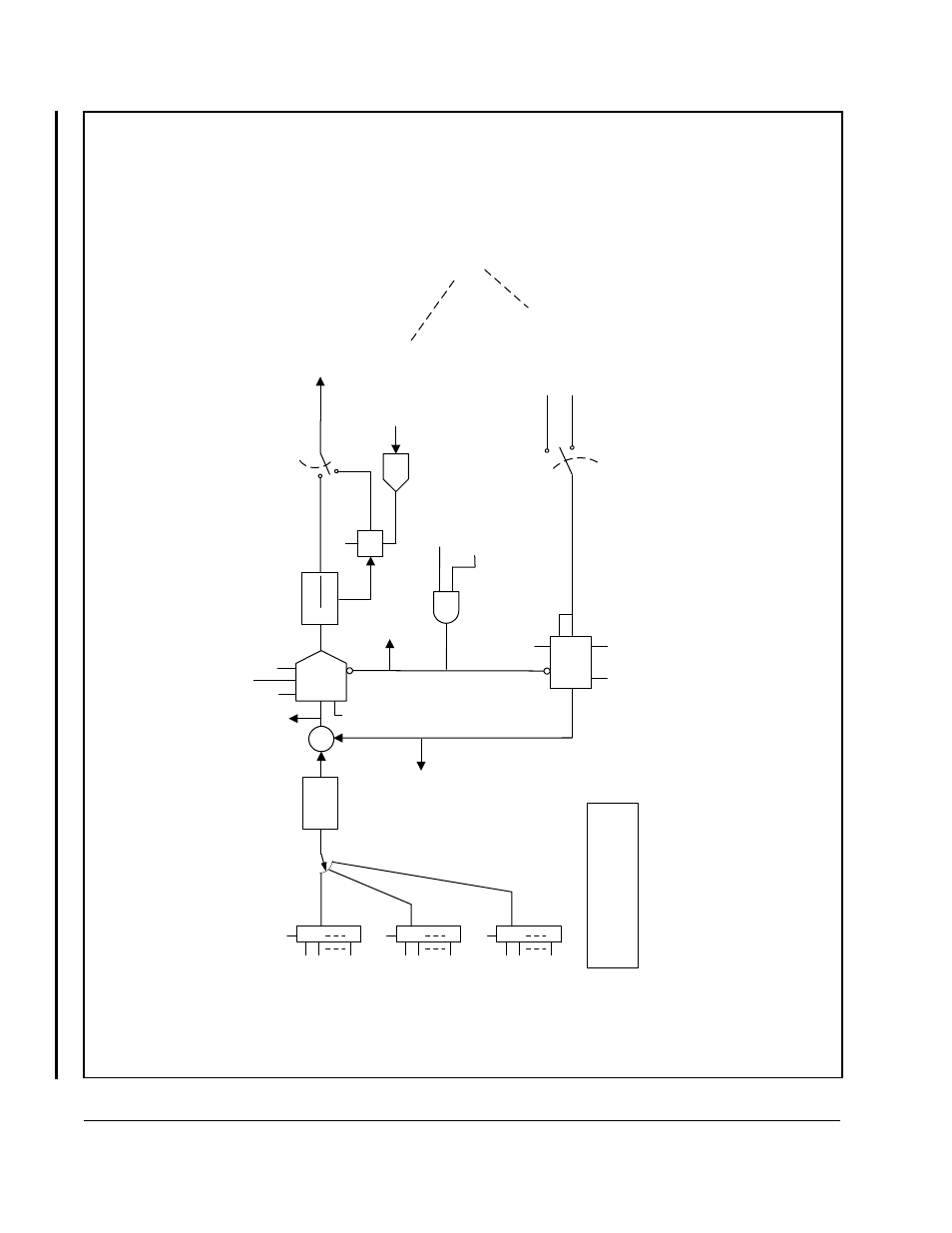
Figure G.7 – Outer Control Loop Block Diagram
O
C
L
output
(to
s
pd
loop
bl
ock
d
iag)
*
Av
ailable
in
netw
o
rk
read
regis
ters
Ki
(U
.046)
+
-
Kp
(U
.045)
PI
In
it
Rst
N
e
tw
O
C
L
enable
b
it
(d1,
r32,
b5)
or
R
M
I
d
igital
input
OCL
L
/L
Ratio
(U
.043)
O
C
L
fdbk
se
le
ct
(U.040)
U
.017
Di
v
(from
s
pd
loop
bl
ock
d
iag)
O
C
LP
ro
pT
ri
m
Enable
(U
.048)
Lead/
Lag
OCL
L
/L
Low
F
req
(U.042)
OCL
L
/L
S
e
le
ct
U.041)
Rst
Input
Speed
PI
O
u
tput
(torque
ref)
Sc
aled
TS
Analog
Input
(4095
@
10v
dc
)
In
it
R
unning
O
C
L
enabled
(d1,
r26,
b2)
*
*
*
*
OCL
feedbac
k
*
0
0
1
ON
OFF
Mu
lt
K
|x|
Spd
ref
S-c
u
rv
e
bloc
k
output
x
U.047
100
x
U
.044
Lim
+
/-4095
B
roadc
as
t
1
0
1
P
.064
8
RM
I
A
nal
og
Input
0
1
P
.064
P
.038
8
P
.031
0
1
P
.064
P
.038
8
P
.031
P
.038
O
p
ti
on
B
oar
d
In
st
a
lle
d
None
RM
I
Networ
k
-
S
e
e
networ
k
s
pec
if
ic
I/M
for
detai
ls
.
B
roadc
as
t
8
Di
re
c
t
20
m
sec
scan
per
iod
See also other documents in the category Rockwell Automation Equipment:
- 20P PowerFlex DC Drive - Frame D Bimetal Thermostat (10 pages)
- 1336S_F_T_E_R F Frame Snubber Resistor Repl. (6 pages)
- 22-COMM PowerFlex 4-Class DSI (Drive Serial Interface) Network Communication Adapter (4 pages)
- 8-545 Plug In Solid State Relay (2 pages)
- 20-HIM-B1 PowerFlex 7-Class HIM Bezel (DPI) (4 pages)
- 100 Contactors with DC Coil (1 page)
- 100 Contactors with DC Coil (2 pages)
- 20P PowerFlex DC Drive - Frame D Switching Power Supply Circuit Board (6 pages)
- 140G-MTFx_MTHx_MTIx_MTKx Trip Unit Installation-140G-M (6 pages)
- 45BRD Analog Laser Sensor (4 pages)
- 20D Multi-Device Interface Option Board for PowerFlex 700S Drives (20 pages)
- 56RF RFID 18 mm Cylindrical Transceiver (2 pages)
- 42KC Miniature Rectangular: 5V DC Version (2 pages)
- 20P PowerFlex DC Drive - Frame A Switching Power Supply Circuit Board (16 pages)
- 21P-MISC-A-TP-2 Transition Tube Kit #C19-6/7 For PowerFlex 755 w/OEM Liquid Cooling Fr 6/7 Drive (2 pages)
- 42BT Background Suppression Sensor (3 pages)
- 42CB High Speed 18mm Cylindrical (4 pages)
- 140EX-JE2_JE3 Molded Case Circuit Breaker (4 pages)
- 140G-K-EAM1A Early Make Aux Contact for Rotary Handle Oper Mech-140G-K (1 page)
- 140G-K-EAM1A Early Make Aux Contact for Rotary Handle Oper Mech-140G-K (3 pages)
- 20-HIM-A6 PowerFlex (Human Interface Module) (74 pages)
- 42CF General Purpose 12mm Cylindrical (4 pages)
- 20D PowerFlex 700S Phase II Drive Frames 1...6 (80 pages)
- 140EX-HE1_HE2 Molded Case Circuit Breaker (6 pages)
- 140EX-HE1_HE2 Molded Case Circuit Breaker (4 pages)
- 20B PowerFlex 700 Custom Firmware - Pump Off (12 pages)
- 20-WIM-N4S DPI Wireless Interface Module (92 pages)
- 140U H-Frame Circuit Breaker Fixed and Adjustable Thermal Trip (7 pages)
- 140U H-Frame Circuit Breaker Fixed and Adjustable Thermal Trip (2 pages)
- 60-2619, 42JS Swivel/Tilt Mounting Bracket (1 page)
- 22A PowerFlex 4/40/400 Flange Mount (4 pages)
- 45MLA Controller Installation Instructions (16 pages)
- 20P PowerFlex DC Drive - Cooling Fan for Frame A Drives Above 73A at 230V 460V AC (6 pages)
- 42JS Series 7000 to 42JS VisiSight Replacement Kit (2 pages)
- 22A PowerFlex 4-Class HIM Bezel (DSI) (4 pages)
- 42CS Stainless Steel Photoelectric Sensors (4 pages)
- 20L-LL PowerFlex 700L Liquid-to-Liquid Heat Exchanger (40 pages)
- 20P PowerFlex DC Drive - Frame B SCR Modules (20 pages)
- 22B PowerFlex 40 Quick Start FRN 5.xx - 6.xx (161 pages)
- 22B PowerFlex 40 Quick Start FRN 5.xx - 6.xx (22 pages)
- 22F PowerFlex 4M Input RFI Filters (2 pages)
- 45LFM Capacitive Label Sensor (4 pages)
- 140G-Rx Installation Instruction-140G-R (2 pages)
- 140G-Rx Installation Instruction-140G-R (29 pages)
- 22C PowerFlex 400 AC Drive Quick Start - FRN 1-4.xx (28 pages)