Command structure – Rockwell Automation 5370 CVIM Communications Manual User Manual
Page 97
Chapter 5
Using the RS-232 Ports
5–27
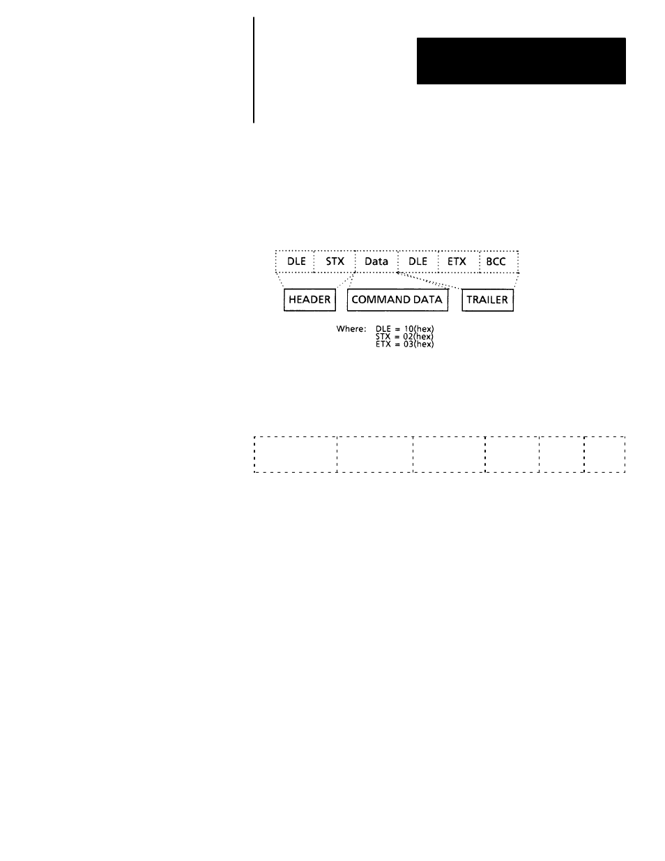
Each command the host device sends to the CVIM module is represented by
a block of data beginning with DLE STX (Data Link Escape, Start of
Transmission) and terminated with DLE ETX BCC (Data Link Escape, End
Transmission, Block Check Character). The data between the header and
trailer characters is the command data. The following shows the structure of
a typical command:
Note: To avoid any confusion between DLE (10 hex) and data equal to 10
(hex), a value of 10(hex) is transmitted as 10(hex) 10(hex). The DLE code is
transmitted simply as 10 (hex). This is referred to as “DLE Stuffing”.
The following shows the typical structure of the command data.
OPERATION n times (H) n times (L) Object Flags Data
There are up to five fields in a command:
Operation Field — This field contains the command directed to the
CVIM module. There can only be one operation per command line. Some
commands don’t require any additional fields while others may require an
object field,a data field, or both. Some commands cannot be used while
the CVIM module is in the SETUP mode. If an operation cannot be
performed because either the wrong host is selected or the CVIM module
is in the SETUP mode, the CVIM module will not send a response.
n times (H) and n times (L) — These two fields indicate the High and
Low bytes of the n times modifier. The n times modifier is used with
certain commands to indicate the number of times the command is to be
performed. The range for this value is 0000 to 00FF (255). A value of
0000 indicates infinity. The default value for this field is 0001.
Object Field — The Object field specifies data that configures the
operation of the CVIM module.
In the description of each command we specify the objects that can
entered into a command.
Flags — This optional field specifies outputs on the local I/O board or
specific blocks of data.
Data Field — Contains data.
Command Structure