Command structure – Rockwell Automation 5370 CVIM Communications Manual User Manual
Page 76
Chapter 5
Using the RS–232 Ports
5–6
•
Symbols:
> (greater than)
* (star)
, (comma)
– (dash)
(space) represented by __
•
Nonprintable control characters:
CR (carriage return)
LF (line feed)
XON
XOFF
•
Numbers 0 through 9
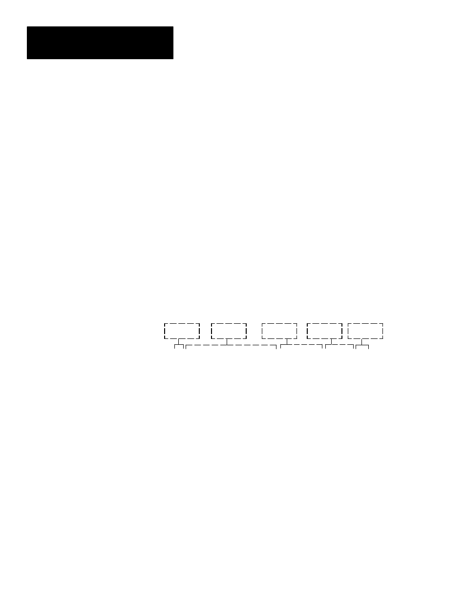
Each command the host device sends to the CVIM module consists of an
ASCII string of characters beginning with > and terminated with a [CR].
Characters in between are separated into fields by commas. The following
shows the structure of a typical command:
> OPERATION (X times), (OBJECT), (DATA) CR
( ) Indicates Optional Information
Header
Field 1
Field 2
Field 3
Trailer
Note: There are two modifiers that may appear in the command line:
x times modifier – This modifier is only used with certain commands to
indicate the number of times the command is to be performed. The range
for this value is between 0 and 255. A value of 0 indicates infinity. If you
do not specify a value, a default of 1 is provided.
Toolset modifier – This modifier specifies either toolset 1 or toolset 2.
TS1 and TS2 are the two valid entries. This modifier is only used to
specify toolset dependent objects.
There are three types of fields:
Operation Field– This field contains commands directed to the CVIM
module. There can only be one operation per command line. Some
operations don’t require any additional fields while others may require an
object field, data field, or both. Note that some commands cannot be used
while the CVIM module is in SETUP mode. If an operation cannot be
performed because either the wrong host port has been selected or the
CVIM module is in the SETUP mode, the CVIM module will respond to
each command with ?[CR][LF].
ASCII Character Set (cont’d)
Command Structure