Accessing discrete bit information – Rockwell Automation 5370 CVIM Communications Manual User Manual
Page 45
Chapter 4
Using the Remote I/O Link
(Node Adapter)
4–8
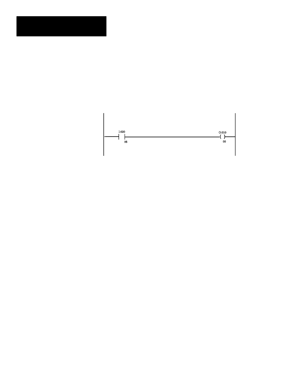
A PLC can directly access discrete bit information using a simple ladder
program. For example:
You can use the following rung to examine the data valid bit and energize an
output if the data is valid. Refer to Chapter 3 for a description of the local
I/O. This example assumes that the CVIM module is in Rack 02 and the
output device is in Rack 01.
Although the same basic information is provided in Appendix B, Tables 4.A
and 4.B illustrate the word and bit locations of the discrete bits that can be
read or manipulated using simple ladder programs. We have organized the
data so that it is formatted similar to a PLC setup screen. Table 4.A shows
the CVIM module Remote Inputs (CVIM module to PLC) if the CVIM
module is rack 02. Table 4.B shows the CVIM module Remote Outputs
(PLC to CVIM module) if the CVIM module is rack 02.
Important Note: To read results data, you must set one of the following bits
(assuming CVIM module is rack 02):
•
O:22/00 (Post First Part of Results to Remote I/O)
•
O:22/01 (Post Second Part of Results to Remote I/O)
Note to PLC–2 Users:
When you use any PLC–2 family processor with the CVIM module, you
should understand the operation of the PLC Block Transfer Done bits for
Read and Write instructions. PLC–2 family processors use the input image
table for these bits, all other PLCs can specify integer files for this function.
This means that a PLC–2 user must use proper programming techniques to
avoid confusion between the following bits:
•
CVIM module discrete I/O input word 0, bit 6 (data valid toolset#1) and
bit 7 (data valid toolset#2).
•
PLC–2 family input image table word 0, bit 6 (BTW done bit) and bit 7
(BTR done bit).
Accessing Discrete
Bit Information