Using output signal timing data – Rockwell Automation 5370 CVIM Communications Manual User Manual
Page 25
Chapter 3
Using Local I/O
3–6
Keep in mind that a completed planning sheet can serve also as a record of
your output line usage. You may find it desirable to store your filled–out
planning sheets in a file folder or loose leaf binder.
To make proper use of the signal data available to the output lines, you must
first understand the timing relationships that exist between the trigger input
signal (which starts each inspection cycle) and the output signals.
Knowing these signal timing relationships enables you to accurately
synchronize the inspection cycles with your production equipment.
Timing charts (Figures 3.2, 3.3, and 3.4) show the timing relationships in
various circumstances.
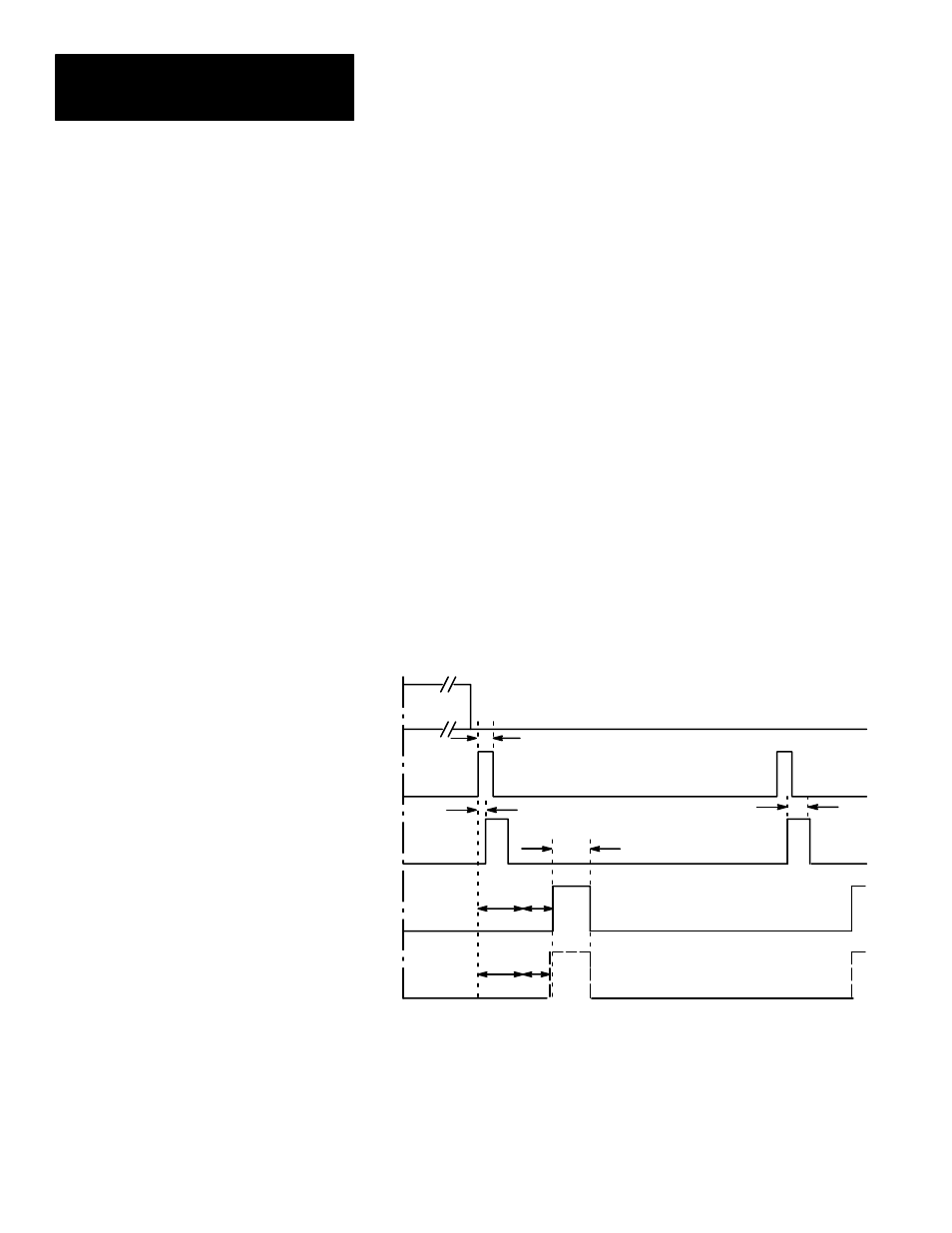
Figure 3.2 shows the relationship between the trigger leading edge and the
Strobe, Data Valid, and Results signals, where the last three appear as pulses
whose duration you determine during configuration.
Figure 3.2
Timing Diagram — Pulsed I/O
Min. strobe
≈
1ms
You can select a
pulse width of 1
to 2000ms
Min. trigger
≈
2ms*
DATA VALID will always
pulse high when inspection
processing is complete.
MODULE
BUSY
*
**
*
**
Trigger
pulse #1
Trigger
pulse #2
Trigger
(Input)
STROBE
DATA
VALID
RESULTS
RESULTS signal will pulse
high if an analysis tool
range limit is exceeded.
Max. lag
≈
1ms
** Minimum acquisition time: 17ms for 256x256 and 512x256 Res; 34 ms for 512x512 res.
*** Analysis time (variable).
Using the Output Line
Planning Sheet (cont’d)
Using Output Signal
Timing Data