Rockwell Automation 1771-QDC, D17716.5.87(Passport) CLAMP AND EJECT MODE User Manual
Page 36
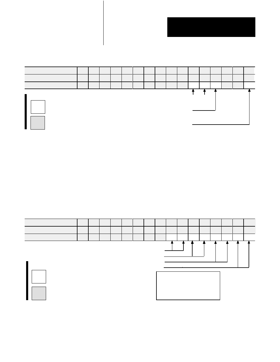
Select System Operation with bits 05 and 04
Clamp and Eject 1 0
Select SingleĆunit Operation with bit 03 = 1
(0 generates a programming error)
Select English = 0 or
metric = 1 with bit 00
Code:
Your value
Required initial value
loaded by ProĆSet 600
0 or 1
Select Input 1 (Ejector Position) Range with bits 01, 00
Select Input 2 (Ejector Pressure) Range with bits 03, 02
Select Input 3 (Clamp Position) Range with bits 05, 04
Select Input 4 (Clamp Pressure) Range with bits 07, 06
Input Range
0 - 10V dc 0 0
1 - 5V dc 0 1
4 - 20 mA 1 0
Not connected 1 1
Code:
Your value
Required initial value
loaded by ProĆSet 600
0 or 1
Configure the QDC Module's
Inputs and Outputs
Chapter 3
3-3
Worksheet 3ĆA
Selecting Module Parameters
Control Word MCC02ĆBxx
15
14 13 12
11
10
09 08 07 06 05 04 03 02 01 00
ProĆSet 600 Addr. B35/bit
543 542 541 540 539 538 537 536 535 534 533 532 531 530 529 528
Value
0
0
0
0
0
0
0
0
0
0
1
0
1
0
0
Example: If you select Clamp and Eject operation with English units:
MCC02 = 00000000 00101000
Selecting I/O Ranges for your Sensors
Next, configure the QDC module’s I/O ranges to match the machine
sensors and valves. Refer to Worksheet 2-A from chapter 2 which you
filled out when setting the QDC module’s jumpers. Apply this information
to Worksheet 3-B for input ranges and Worksheet 3-C for output ranges.
Worksheet 3ĆB
Selecting Input Ranges for your Sensors
Control Word MCC03ĆBxx
15
14 13 12 11
10
09 08 07 06 05 04 03 02 01 00
ProĆSet 600 Addr. B35/bit
559 558 557 556 555 554 553 552 551 550 549 548 547 546 545 544
Value
1
1
1
1
1
1
1
1
Example: If you select an input range of 4-20mA for all four inputs,
MCC03 = 11111111 10101010.
Important: Software input/output selections must match the jumper
settings for each respective input/output.