7ć37 – Rockwell Automation 1771-QDC, D17716.5.87(Passport) CLAMP AND EJECT MODE User Manual
Page 113
Load Initial Configuration Values
Chapter 7
7-37
Selected Velocity Valve Output for Maximum
(FCC48, SCC48, TCC48, FOC48, SOC48, TOC48, OSC48, EAC48, ERC48)
This word operates in conjunction with the minimum velocity control limit
(word 46). Enter in this word the signal output percentage that the QDC
module uses to drive the selected velocity valve to maximum velocity
during any velocity vs. position profile or stroke. The QDC module
expects a velocity equal to word 46 when setting the selected velocity
valve to this percentage output.
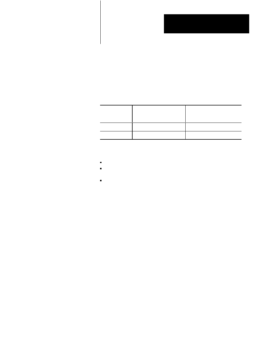
If your selected
velocity valve is:
Then the value in word 48
should be:
And during the profile or stroke,
the QDC module does not drive
the valve with a % output:
Direct Acting
greater than the value in word 47 greater than word 48
Reverse Acting
less than the value in word 47
less than word 48
Reference the above chart and enter one of the following for each Selected
Velocity Valve Maximum Output:
9999 (100%) for uni-directional direct acting valves
0 (0%) or 9999 (100%) for bi-directional valves(dependant upon desired
direction of motion)
0 (0%) for uni-directional reverse acting valves
The valve spanning procedures presented in chapter 9 require these initial
values in order to assist you in selecting the correct, final values required
by your application. Refer to Section 3 of the Plastic Molding Module
Reference Manual (pub. no. 1771-6.5.88) for more information.
Profile Gain Constants
(FCC49 Ć 53, SCC49 Ć 53, TCC49 Ć 53, LPC49 Ć 51, FOC49 Ć 53, SOC49 Ć 53,
TOC49 Ć 53, OSC49 Ć 53, EAC49 Ć 53, ERC49 Ć 53)
The QDC module’s PID and velocity feedforward(VelFF) algorithms are
different from classic PID and VelFF algorithms. The algorithm gain
constants are typically lower than those used to control a traditional
process that reacts to setpoints changes.
Enter the default values from the worksheets for all Profile Tuning
Constants. The closed-loop tuning procedures presented in chapter 10
require these initial values in order to assist you in selecting the correct,
final values required by your application. Refer to Section 3 of the Plastic
Molding Module Reference Manual (pub. no. 1771-6.5.88) for more
information.
Set Profile Gain Constants
and Pressure Alarm
Setpoints