Rockwell Automation 25B PowerFlex 525 Embedded EtherNet/IP Adapter User Manual
Page 92
92
Rockwell Automation Publication 520COM-UM001B-EN-E - March 2013
Chapter 7
Using Multi-Drive Mode
8.
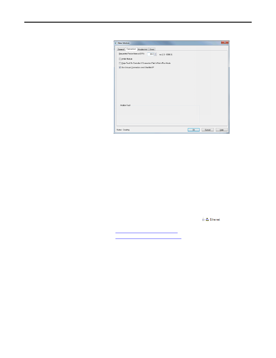
On the New Module window, click the Connection tab.
9.
In the “Requested Packet Interval (RPI)” box, set the value to 5.0
milliseconds or greater. This value determines the maximum interval that a
controller should use to move data to and from the adapter. To conserve
bandwidth, use higher values for communicating with low priority devices.
The “Inhibit Module” box, when checked, inhibits the module from
communicating with the RSLogix 5000/Logix Designer project. When
the “Major Fault on …” box is checked, a major controller fault will occur
when the module’s connection fails while the controller is in the Run
Mode. For this example, leave the “Inhibit Module” and “Major Fault On
…” boxes unchecked.
10.
Click OK on the New Module window.
The new node (“PowerFlex 525-EENET-Multi PowerFlex_52X_Drive-
Multi” in this example) now appears under the
icon in the I/O
Configuration folder. If you double-click on the Input Controller Tag
(
Controller Input Tags on page 93
) and Output Controller Tag
(
Controller Output Tags on page 94
), you will see that module-defined
data types and tags have been automatically created. Note that all tag
names are defined for each drive. After you save and download the
configuration, these tags allow you to access the Input and Output data of
the drives using the controller’s ladder logic.