Rockwell Automation 25B PowerFlex 525 Embedded EtherNet/IP Adapter User Manual
Page 74
74
Rockwell Automation Publication 520COM-UM001B-EN-E - March 2013
Chapter 6
Using Explicit Messaging
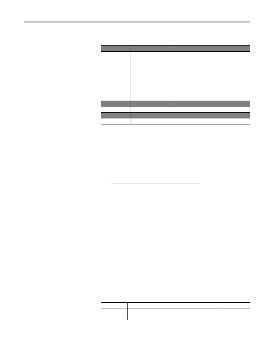
The following table identifies the data that is required in each box to configure a
message to write a single parameter.
CompactLogix Example Ladder Logic Program to Read Multiple
Parameters
A Scattered Read message is used to read the values of multiple parameters. This
read message example reads the values of these five 16-bit parameters in a
PowerFlex 525 drive:
•
Parameter b001[Output Freq]
•
Parameter b003 [Output Current]
•
Parameter b004 [Output Voltage]
•
Parameter b005 [DC Bus Voltage]
•
Parameter b017 [Output Power]
Example Controller Tags to Read Multiple Parameters
Configuration Tab
Example Value
Description
Message Type
Service Type
(1)
Service Code
(1)
Class
Instance
(2)
Attribute
(3)
Source Element
Source Length
Destination
(1) The default setting for Service Type is “Custom,” enabling entry of a Service Code not available from the Service Type pull-down
menu. When choosing a Service Type other than “Custom” from the pull-down menu, an appropriate Hex. value is automatically
assigned to the Service Code box which is dimmed (unavailable).
(2) The instance is the parameter number in the drive.
(3) Setting the Attribute value to “9” will write the parameter value to the drive’s Non-Volatile Storage (EEPROM) memory, so the
parameter value will remain even after the drive is power cycled. Important: When set to “9,” be very cautious as the EEPROM may
quickly exceed its life cycle and cause the drive to malfunction. Setting the Attribute value to “A” will write the parameter value to
temporary memory, so the parameter value will be lost after the drive is power cycled. It is recommended to use the “A” setting
when frequent write messages are required. Important: If you need to make frequent parameter changes using Explicit Messages,
set parameter C121 [Comm Write Mode] to 1 “RAM only”.
CIP Generic
Get Attribute Single
10 (Hex.)
93
(5)
41 (Dec.)
9 or A (Hex.)
Accel_Time_1
(6)
2 bytes
–
(5) See
Explicit Messaging Class Code Compatibility with PowerFlex 525 Drives on page 70
for limitations of PowerFlex 525 drives when
using DPI Parameter Object Class code 0x93 for explicit messaging.
(6) In this example, Accel Time 1 is a 16-bit parameter requiring the Data Type field to be set to “INT” when creating the controller tag.
Also, the Source Length field on the Message Configuration screen must correspond to the selected Data Type in bytes (for example,
2 bytes for an INT). See the drive documentation to determine the size of the parameter and its data type.
Used to access the DPI Parameter Object in the adapter.
This service is used to read a parameter value.
Code for the requested service.
Class ID for the DPI Parameter Object.
Instance number is the same as parameter number.
Attribute number for the Parameter Value attribute.
Name of the tag for any service data to be sent from the scanner
or bridge to the drive.
Number of bytes of service data to be sent in the message.
Leave blank (not applicable).
Communication Tab Example Value
Description
Path
(4)
(4) Click Browse to find the path, or type in the name of the device listed in the I/O Configuration folder (for this example,
PowerFlex_52X_Drive).
PowerFlex_52X_Drive
The path is the route that the message will follow.
Tag Tab
Example Value
Description
Name
Single_Write_Message
The name for the message.
Operation
Controller Tags for Scattered Read Message
Data Types
XIC
Execute_Scattered_Read_Message
BOOL
MSG
Scattered_Read_Message
MESSAGE