Rockwell Automation 25B PowerFlex 525 Embedded EtherNet/IP Adapter User Manual
Page 54
54
Rockwell Automation Publication 520COM-UM001B-EN-E - March 2013
Chapter 4
Configuring the I/O
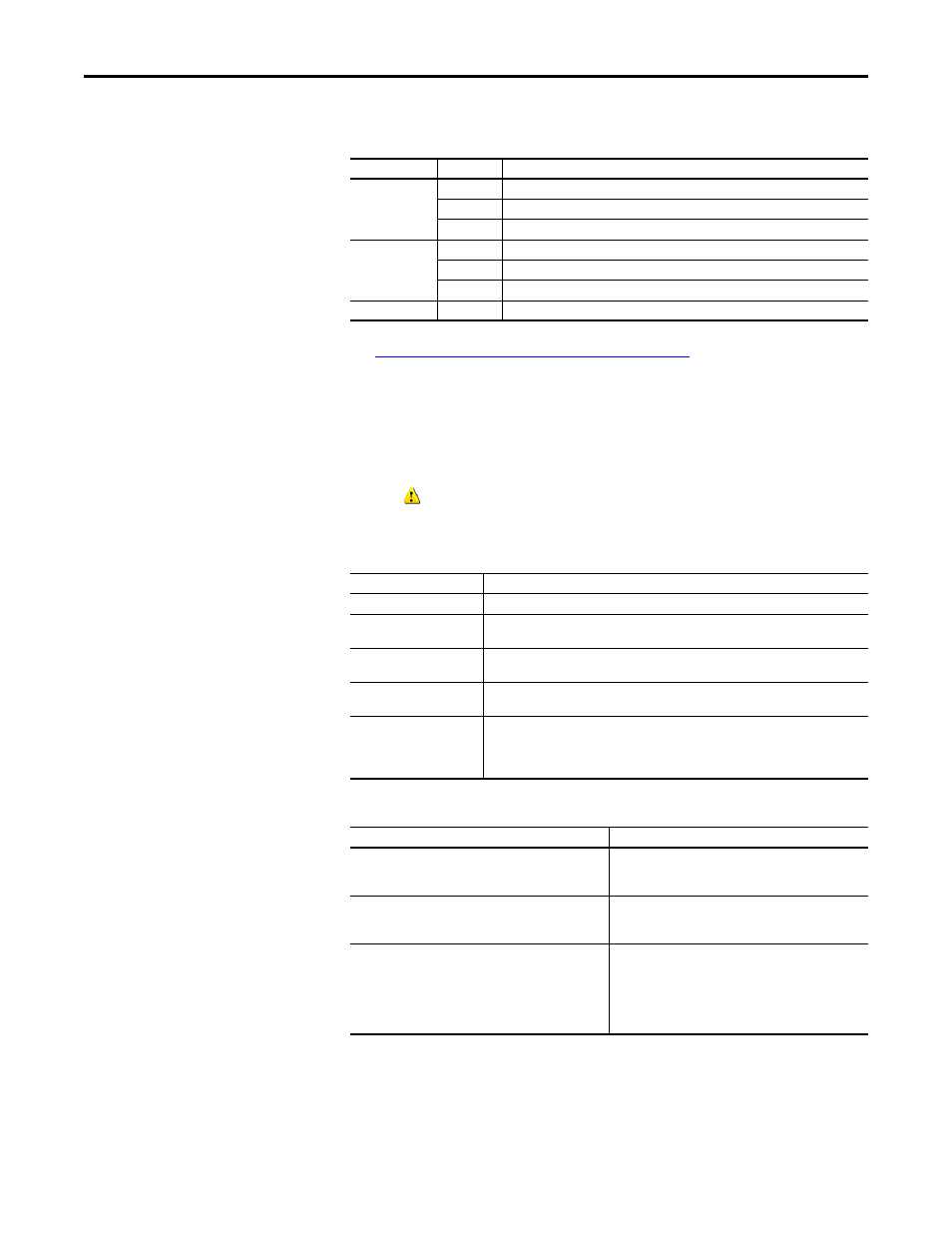
An operational drive in a running Logix system will have the following status
indicator states:
Understanding the Status Indicators on page 111
for more information.
Additional information may also be displayed on the HIM if it is present (flash
status, etc.).
If ADC is unsuccessful, RSLogix 5000/Logix Designer can be used to get
additional information. When online, the drive at issue should have a yellow
triangle
next to it in the RSLogix 5000/Logix Designer project's I/O
Configuration folder. Double-click on the drive to open the drive AOP. The
Connection tab will show a Module Fault code and the Drive tab can help you
identify issues.
Examples of potential issues/solutions are:
Status Indicator State
Description
ENET
Off
Adapter is not connected to the network.
Steady
Adapter is connected to the network and drive is controlled through Ethernet.
Flashing
Adapter is connected to the network but drive is not controlled through Ethernet.
LINK
Off
Adapter is not connected to the network.
Steady
Adapter is connected to the network but not transmitting data.
Flashing
Adapter is connected to the network and transmitting data.
FAULT
Flashing Red Indicates drive is faulted
ADC Status Field
Description
Running
Any desired configuration is complete, and the I/O connection is running.
Configuring
ADC is currently updating the configuration of the drive or one of its peripherals. Clicking
on the Connection tab will show which device is being updated.
Firmware Updating
ADC is currently updating the firmware of the drive or one of its peripherals. Clicking on
the Drive tab will show which device is being updated.
Inhibited
The program has the connection inhibited. You can uninhibit the connection on the
Connection tab.
Faulted
A problem is preventing the controller from connecting to the drive (for example, the
device at the IP address provided is not a PowerFlex 525 drive). Clicking on the
Connection tab will show the cause (Module Fault). Clicking on the Drive tab may also
show the faulted ports.
Issue
Solution
“Compatible module” keying selected, but replacement
drive or peripheral has an earlier firmware revision than the
failed device.
Replace device with a revision that is later than or equal to
the failed device. If necessary, use ControlFLASH to flash
replacement device first to an acceptable revision level.
Peripheral is required for connection (“Fail Drive Connection
on Peripheral Error” was checked), but it is missing.
Add required peripheral or remove peripheral from
RSLogix 5000/Logix Designer project for the drive and
download project to the controller.
Parameter “out of range” error—ADC wrote a value to a
parameter that was out of range (typically would only
occur during initial commissioning of a drive system).
Use any available drive software tool to view a linear list of
changed parameters to see if the configured value is
outside the minimum/maximum value. The drive AOPs are
the preferred tool and will highlight any out of range
parameter in the Linear List editor. Connected Components
Workbench (version 3 or later) may also be used.