Rockwell Automation 25B PowerFlex 525 Embedded EtherNet/IP Adapter User Manual
Page 44
44
Rockwell Automation Publication 520COM-UM001B-EN-E - March 2013
Chapter 4
Configuring the I/O
C160 [EN Data Out 4]
to point to the appropriate drive or connected
peripheral parameters. The procedure to configure the Datalinks on the
Module Definition window for the Input Data and Output Data is the
same:
•
Click the
button to assign a parameter to each input and output
Datalink you require.
6.
Click OK on the Module Definition window to save the drive
configuration and close the window. The drive’s New Module window
reappears.
7.
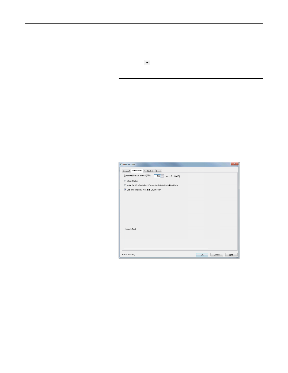
On the New Module window, click the Connection tab.
8.
In the “Requested Packet Interval (RPI)” box, set the value to 5.0
milliseconds or greater. This value determines the maximum interval that a
controller should use to move data to and from the adapter. To conserve
bandwidth, use higher values for communicating with low priority devices.
The “Inhibit Module” box, when checked, inhibits the module from
communicating with the RSLogix 5000/Logix Designer project. When
the “Major Fault on …” box is checked, a major controller fault will occur
when the module’s connection fails while the controller is in the Run
Mode. For this example, leave the “Inhibit Module” and “Major Fault On
…” boxes unchecked.
IMPORTANT
Always use the Datalink parameters in consecutive numerical order,
starting with the first parameter. (For example, use parameters C157,
C158, and C159 to configure three Datalinks to write data and/or
parameters C153, C154, C155, and C156 to configure four Datalinks to
read data.) Otherwise, the network I/O connection will be larger than
necessary, which needlessly increases controller response time and
memory usage.