Rockwell Automation 25B PowerFlex 525 Embedded EtherNet/IP Adapter User Manual
Page 56
56
Rockwell Automation Publication 520COM-UM001B-EN-E - March 2013
Chapter 4
Configuring the I/O
3.
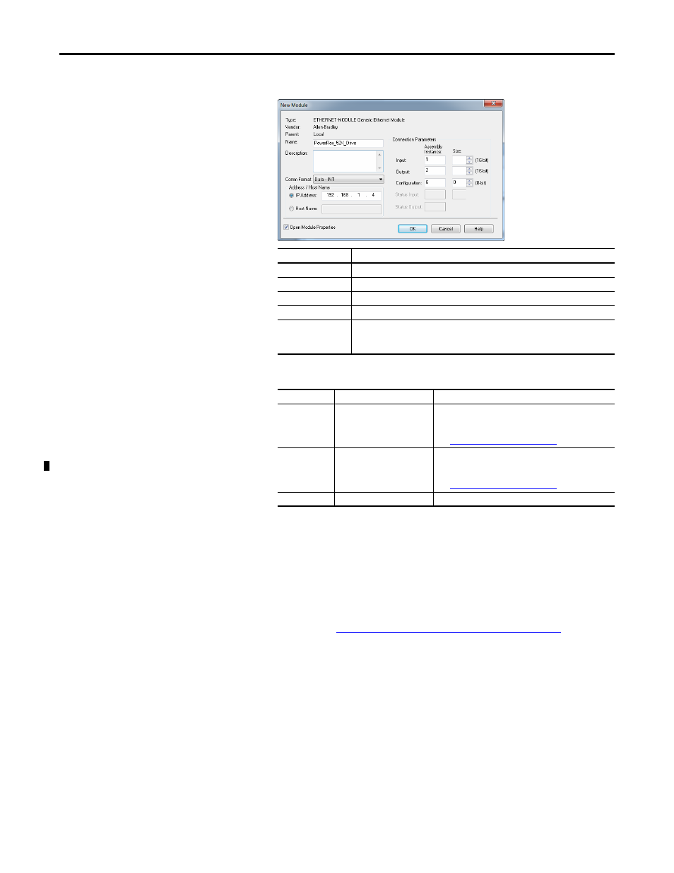
Edit the following information about the drive:
4.
Under Connection Parameters, edit the following:
Enter the number of 16-bit words that are required for your I/O in the
Input Size and Output Size boxes. Since the adapter always uses the 16-bit
Logic Status, 16-bit Feedback, and two 16-bit words dedicated for
memory allocation of the Generic Ethernet module profile, at least four
16-bit words must be set for the Input Size. The adapter also uses the 16-
bit Logic Command and 16-bit Reference, requiring at least two 16-bit
words for the Output Size. If any or all of the drive’s eight 16-bit Datalinks
are used (see
Configuring a Master-Slave Hierarchy on page 31
), the Input
and Output Size settings must be increased accordingly.
Box
Setting
Name
A name to identify the drive.
Description
Optional – description of the drive.
Comm Format
Data – INT (This setting formats the data in 16-bit words.)
IP Address
The IP address of the drive.
Open Module
Properties
When this box is checked, clicking OK opens additional module properties screens to
further configure the drive. When unchecked, clicking OK closes the drive’s New
Module screen. For this example, check this box.
Box
Assembly Instance
Size
Input
1 (This value is required.)
The value will vary based on the total number of [EN Data
Out x] parameters used for your application, either in
Single-drive mode (see details below) or Multi-drive mode
(see
Using Multi-Drive Mode on page 83
).
Output
2 (This value is required.)
The value will vary based on the total number of [EN Data
In x] parameters used for your application, either in
Single-drive mode (see details below) or Multi-drive mode
(see
Using Multi-Drive Mode on page 83
).
Configuration
6 (This value is required.)
0 (This value is required.)