Drive 1 control routine – Rockwell Automation 25B PowerFlex 525 Embedded EtherNet/IP Adapter User Manual
Page 103
Rockwell Automation Publication 520COM-UM001B-EN-E - March 2013
103
Using Multi-Drive Mode
Chapter 7
Drive 1 Control Routine
0
5
(End)
Copy File
Source
Dest
Length
Drive_Input_Image[5]
Drive_1_Feedback
1
COP
12
Copy File
Source
Dest
Length
Drive_1_Reference
Drive_Output_Image[3]
1
COP
15
Return from Subroutine
RET
Drive_Input_Image[4].0
Drive_1_Status_Ready
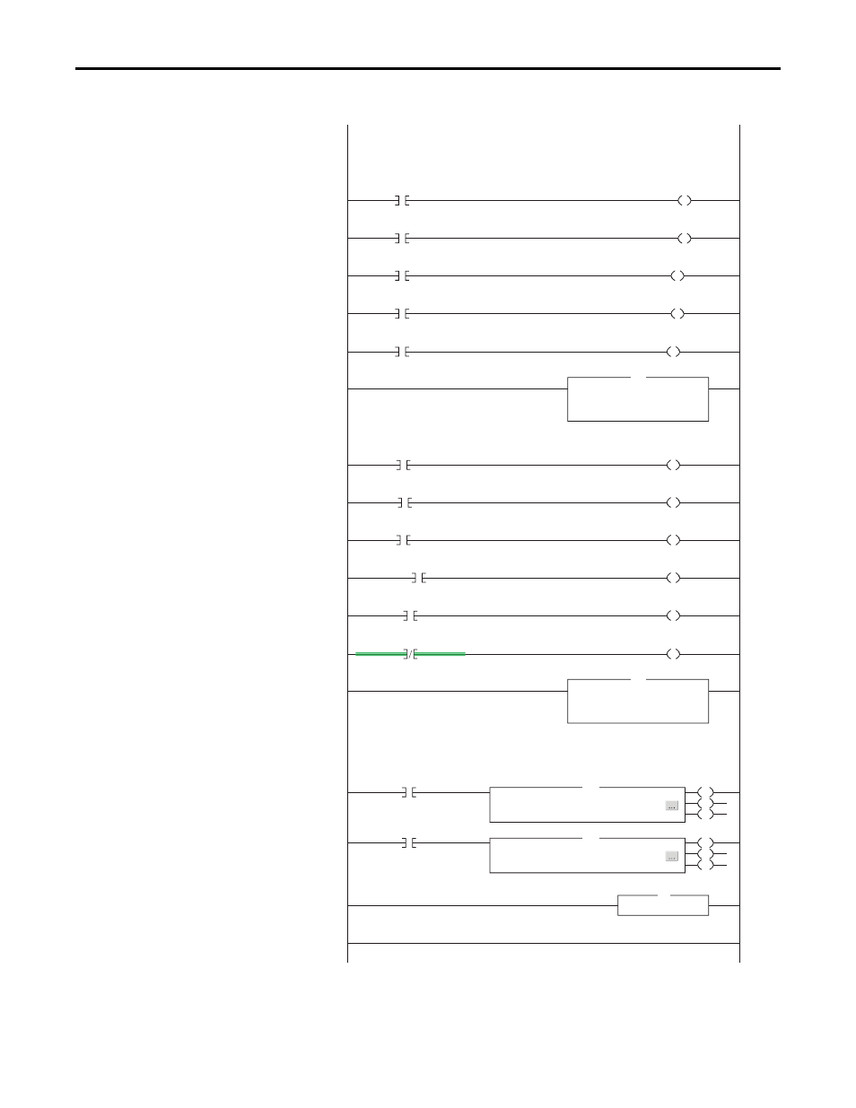
This section takes the data from the input area and moves it to specific tags (Logic Status bits and Feedback) for use
elsewhere in the ladder program.
This section takes the data from specific tags (Logic Command bits and Reference) and moves them to the output
image area for transmission to the scanner.
Drive 1 parameters are accessed by adding 17408 decimal (4400 hex) to the desired parameter number. For example,
to access parameter P109 an Instance of 17517 (17408 + 109) is used.
1
Drive_Input_Image[4].1
Drive_1_Status_Active
2
Drive_Input_Image[4].3
Drive_1_Status_Forward
3
Drive_Input_Image[4].7
Drive_1_Status_Faulted
4
Drive_Input_Image[4].8
Drive_1_Status_At_Reference
6
Drive_1_Command_Stop
Drive_Output_Image[2].0
7
Drive_1_Command_Start
Drive_Output_Image[2].1
8
Drive_1_Command_Jog
Drive_Output_Image[2].2
9
Drive_1_Command_Clear_Faults
Drive_Output_Image[2].3
10
Drive_1_Command_Forward
Drive_Output_Image[2].4
13
Perform_Parameter_Read_1
EN
DN
ER
11
Drive_1_Command_Forward
Drive_Output_Image[2].5
Message
Message Control Parameter_RD_Message_1
MSG
14
Perform_Parameter_Write_1
EN
DN
ER
Message
Message Control Parameter_WR_Message_1
MSG
Explicit Messaging Example
Drive 1 Control Subroutine