Rockwell Automation 25B PowerFlex 525 Embedded EtherNet/IP Adapter User Manual
Page 160
160
Rockwell Automation Publication 520COM-UM001B-EN-E - March 2013
Glossary
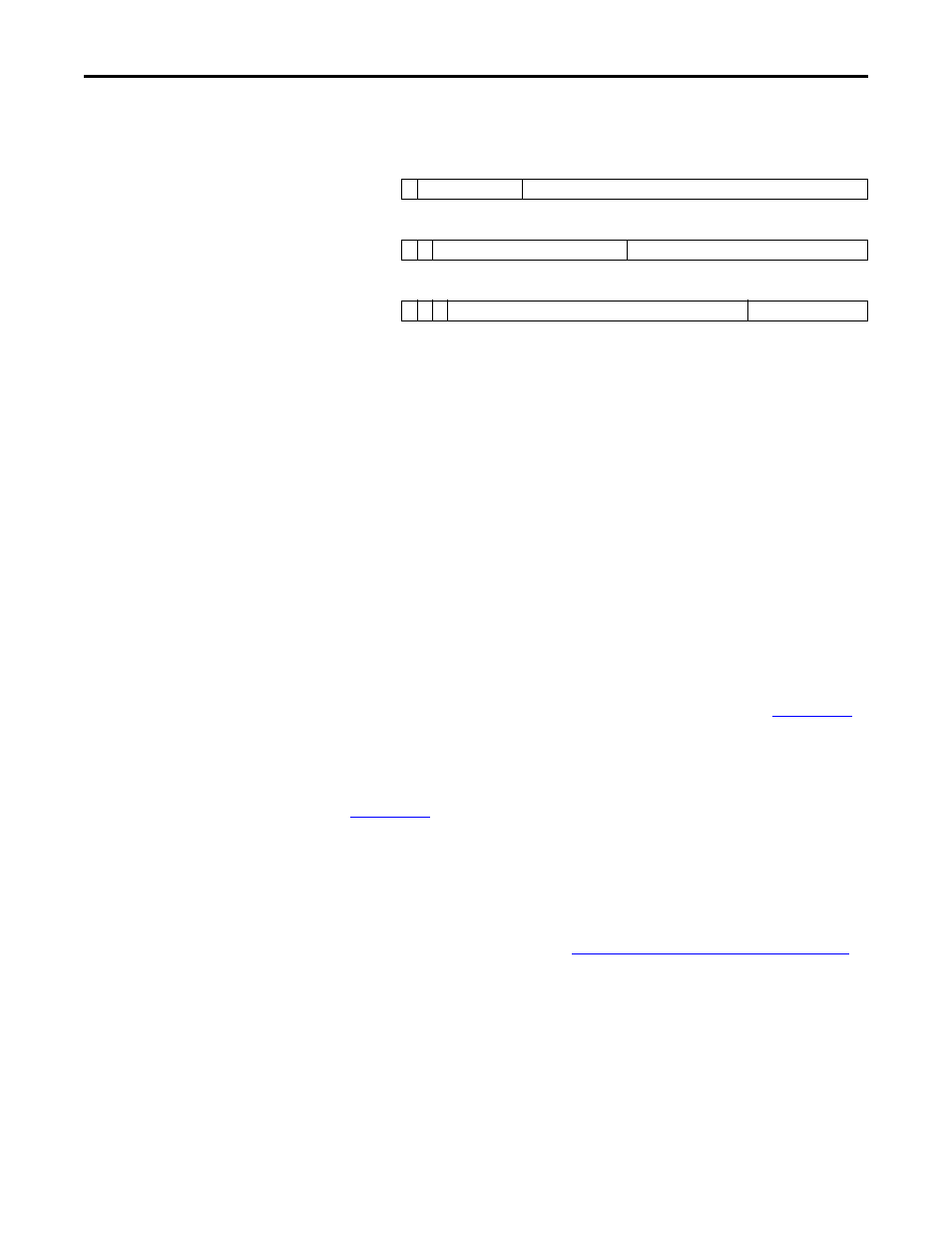
An IP address has two parts: a network ID and a host ID. The class of network
determines the format of the address.
The number of devices on your EtherNet/IP network will vary depending on the
number of bytes that are used for the network address. In many cases you are
given a network with a Class C address, in which the first three bytes contain the
network address (subnet mask = 255.255.255.0). This leaves 8 bits or 256
addresses on your network. Because two addresses are reserved for special uses (0
is an address for the network usually used by the router, and 255 is an address for
broadcast messages to all network devices), you have 254 addresses to use on a
Class C address block.
To ensure that each device on the Internet has a unique address, contact your
network administrator or Internet Service Provider for unique fixed IP addresses.
You can then set the unique IP address for the adapter by using a BootP server or
by manually configuring parameters in the adapter. The adapter reads the values
of these parameters only at power-up.
Logic Command/Logic Status
The Logic Command is used to control the PowerFlex 525 drive (for example,
start, stop, direction). It consists of one 32-bit word of output to the adapter from
the network. The definitions of the bits in this word are shown in
.
The Logic Status is used to monitor the PowerFlex 525 drive (for example,
operating state, motor direction). It consists of one 32-bit word of input from the
adapter to the network. The definitions of the bits in this word are shown in
Logix Designer
The Logix Designer application is the rebranding of RSLogix 5000 software and
will continue to be the product to program Logix 5000 controllers for discrete,
process, batch, motion, safety, and drive-based solutions. It is a 32-bit application
that runs on various Windows operating systems. Information about Logix
Designer software can be found at
.
Master-Slave Hierarchy
An adapter configured for a master-slave hierarchy exchanges data with the
master device. Usually, a network has one scanner which is the master device, and
all other devices (for example, drives connected to EtherNet/IP adapters) are
slave devices.
On a network with multiple scanners (called a multi-master hierarchy), each slave
device must have a scanner specified as a master.
0 1
7
15
23
31
Class A
0 Network ID
Host ID
0 1
7
15
23
31
Class B
1 0 Network ID
Host ID
0 1 2
7
15
23
31
Class C
1 1 0 Network ID
Host ID