Status indicators – Rockwell Automation 25B PowerFlex 525 Embedded EtherNet/IP Adapter User Manual
Page 15
Rockwell Automation Publication 520COM-UM001B-EN-E - March 2013
15
Getting Started
Chapter 1
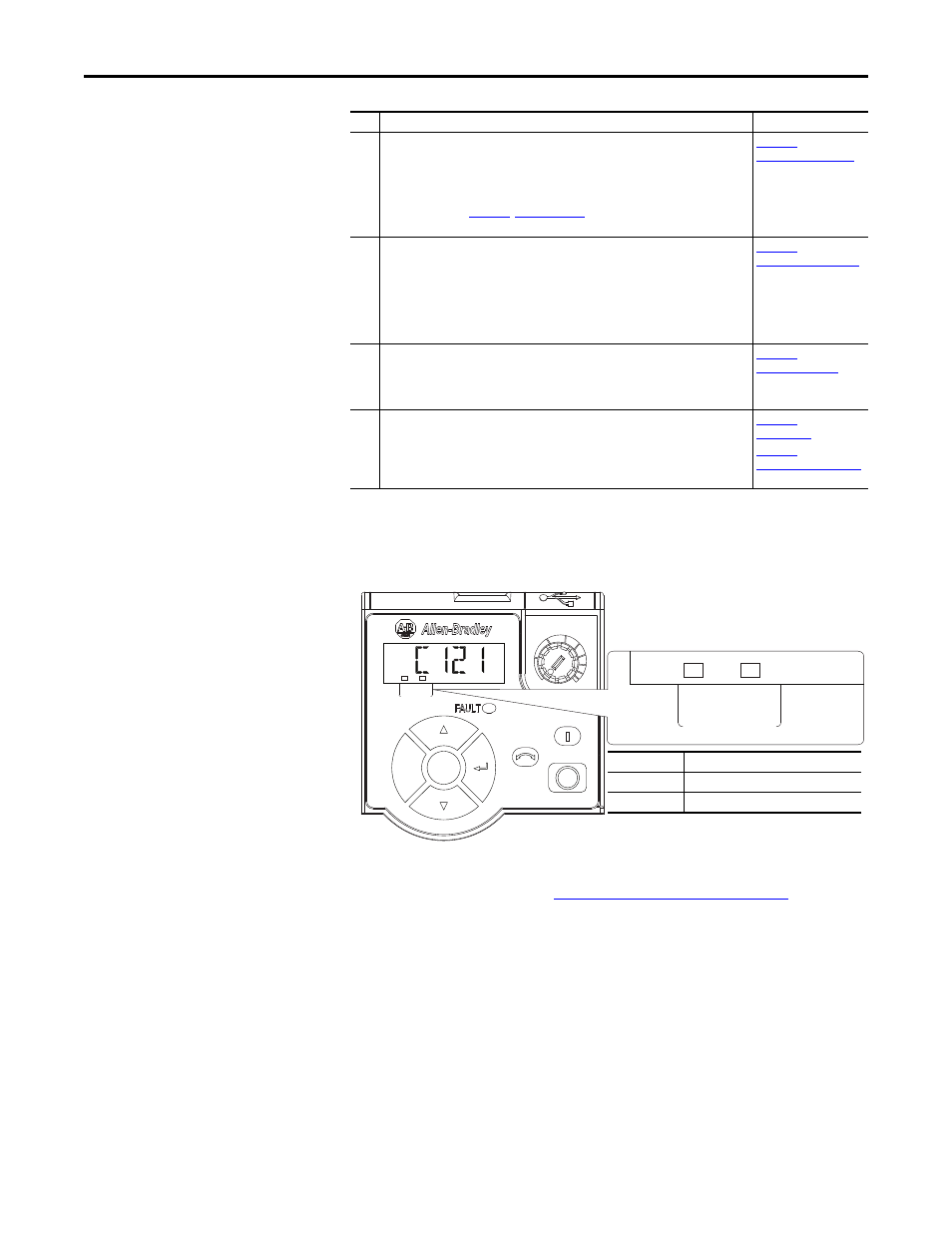
Status Indicators
The embedded EtherNet/IP adapter uses two status indicators to report its
operating status.
After connecting the embedded EtherNet/IP adapter to the network and
applying power to the drive, see
Startup Status Indication on page 19
for possible
start-up status indications and their descriptions.
4
Apply power to the drive.
a. Replace the control module cover.
b. The embedded EtherNet/IP adapter receives power from the drive. Apply power
to the drive. The ENET/LINK status indicators on the drive’s LCD display should
light up and remain steady or flash. If the drive’s Fault LED lights up, there is a
problem. See
c. Configure/verify key drive parameters.
5
Configure the adapter for your application.
Set drive parameters for the following functions as required by your application:
– IP address, subnet mask, and gateway address
– Data rate
– I/O configuration
– Master-Slave hierarchy
– Fault actions
6
Configure the controller to communicate with the adapter.
Use a controller configuration tool such as RSLogix 5000/Logix Designer to configure
the master on the EtherNet/IP network to recognize the embedded EtherNet/IP
adapter and drive.
7
Create a ladder logic program.
Use a controller configuration tool such as RSLogix 5000/Logix Designer to create a
ladder logic program that enables you to:
– Control the embedded EtherNet/IP adapter and drive using I/O.
– Monitor or configure the drive using Explicit messages.
Step Action
See...
Esc
Sel
FWD
ENET LINK
EtherNet/IP
ENET LINK
EtherNet/IP
Item
Name
➊
ENET indicator
➋
LINK indicator
➊
➋