Using the i/o, About i/o messaging, Understanding the i/o image – Rockwell Automation 25B PowerFlex 525 Embedded EtherNet/IP Adapter User Manual
Page 61: Chapter 5, About i/o messaging understanding the i/o image, Chapter
Rockwell Automation Publication 520COM-UM001B-EN-E - March 2013
61
Chapter
5
Using the I/O
This chapter provides information and examples that explain how to control,
configure, and monitor a PowerFlex 525 drive using the configured I/O.
About I/O Messaging
On CIP-based networks, including EtherNet/IP, I/O connections are used to
transfer the data which controls the PowerFlex drive and sets its Reference. I/O
can also be used to transfer data to and from Datalinks in PowerFlex 525 drives.
The adapter includes the Logic Command, Logic Status, Reference, Feedback,
and memory allocation for the Generic Ethernet module profile (all as 16-bit
words) in the controller’s I/O image. This basic I/O must always be configured in
the Ethernet bridge using RSLogix 5000/Logix Designer. Additional I/O, if
needed, can be set using up to four Datalinks to write data and/or up to four
Datalinks to read data. When using any combination of these Datalinks, add one
16-bit word for each Datalink to the basic I/O Input Size and/or Output Size.
discuss how to configure the adapter and controller on the network for the
required I/O. The Glossary defines the different options. This chapter discusses
how to use I/O after you have configured the drive and controller.
Understanding the I/O Image
The terms
input and output are defined from the controller’s point of view.
Therefore, output I/O is data that is produced by the controller and consumed by
the adapter. Input I/O is data that is produced by the adapter and consumed as
input by the controller. The I/O image will vary based on:
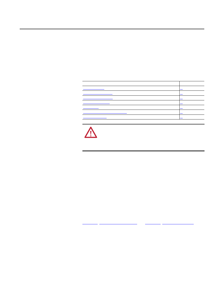
Topic
Page
Example Ladder Logic Program Information
ATTENTION: Risk of injury or equipment damage exists. The examples in this
publication are intended solely for purposes of example. There are many
variables and requirements with any application. Rockwell Automation, Inc.
does not assume responsibility or liability (to include intellectual property
liability) for actual use of the examples shown in this publication.